DESCRIPTION The speed
sensor detects the wheel speed and sends the appropriate signals to the
skid control ECU. The skid control ECU converts these wheel speed
signals into a pulse signal and outputs it to the ECM via the
combination meter. The ECM determines the vehicle speed based on the
frequency of this pulse signal. 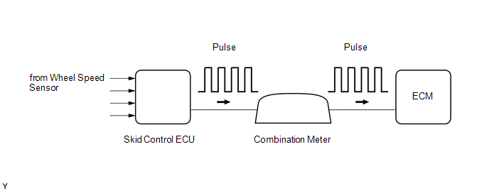 |
DTC No. | DTC Detection Condition |
Trouble Area | | P0500 |
While vehicle being driven, no vehicle speed sensor signal transmitted to ECM
(2 trip detection logic) |
- Open or short in speed signal circuit
- Wheel speed sensor
- Combination meter
- ECM
- Skid control ECU
| MONITOR DESCRIPTION
The
ECM assumes that the vehicle is being driven when the indicated vehicle
speed is more than 9 km/h (5.6 mph). If there is no speed signal from
the combination meter despite this condition being met, the ECM
interprets this as a malfunction in the speed signal circuit. The ECM
then illuminates the MIL and stores the DTC. MONITOR STRATEGY |
Related DTCs | P0500: Vehicle speed sensor "A" pulse input error | |
Required Sensors/Components (Main) | Vehicle Speed Sensor (VSS), Combination meter and Skid control ECU | |
Required Sensors/Components (Related) |
Park/Neutral
Position (PNP) switch, Engine Coolant Temperature (ECT) sensor,
Crankshaft Position (CKP) sensor, Throttle Position (TP) sensor and Mass
Air Flow (MAF) meter | | Frequency of Operation |
Continuous | | Duration |
5 seconds | | MIL Operation |
2 driving cycles | | Sequence of Operation |
None | TYPICAL ENABLING CONDITIONS |
Monitor runs whenever following DTCs not present |
None | | Time after ignition switch off to ON |
3 seconds or more | | Vehicle speed |
9 km/h (5.59 mph) or more | |
Battery voltage | 8 V or more | |
Starter | OFF | TYPICAL MALFUNCTION THRESHOLDS |
Vehicle speed sensor signal | No pulse input | CONFIRMATION DRIVING PATTERN
- Connect the Techstream to the DLC3.
- Turn the ignition switch to ON and turn the Techstream on.
- Clear DTCs (even if no DTCs are stored, perform the clear DTC operation).
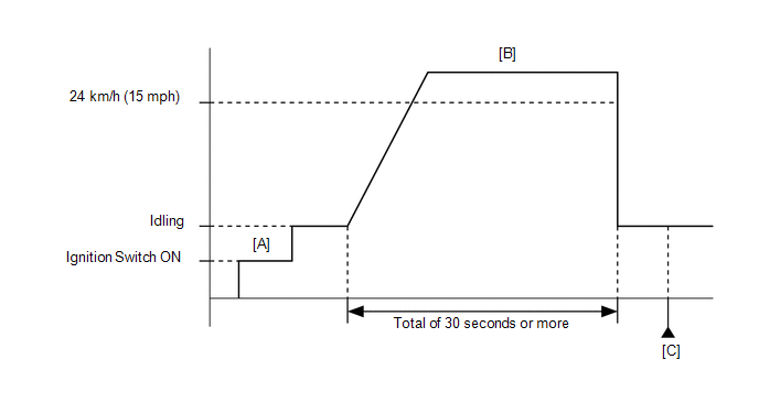
- Turn the ignition switch off and wait for at least 30 seconds.
- Turn the ignition switch to ON and turn the Techstream on [A].
- Start the engine.
- Drive the vehicle at 24 km/h (15 mph) or more for a total of 30 seconds or more [B].
- Stop the vehicle.
- Enter the following menus: Powertrain / Engine and ECT / Trouble Codes [C].
- Read the pending DTCs.
HINT:
- If a pending DTC is output, the system is malfunctioning.
- If a pending DTC is not output, perform the following procedure.
- Enter the following menus: Powertrain / Engine and ECT / Utility / All Readiness.
- Input the DTC: P0500.
- Check the DTC judgment result.
|
Tester Display |
Description |
|
NORMAL |
- DTC judgment completed
- System normal
|
|
ABNORMAL |
- DTC judgment completed
- System abnormal
|
|
INCOMPLETE |
- DTC judgment not completed
- Perform driving pattern after confirming DTC enabling conditions
|
|
N/A |
- Unable to perform DTC judgment
- Number of DTCs which do not fulfill DTC preconditions has reached ECU memory limit
|
HINT:
If the judgment result shows ABNORMAL, the system has a malfunction.
- If the test result is INCOMPLETE or N/A and no pending DTC is output,
perform a universal trip and check for permanent DTCs (See page
 ). ).
HINT:
- If a permanent DTC is output, the system is malfunctioning.
- If no permanent DTC is output, the system is normal.
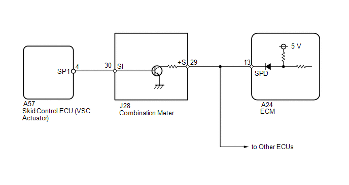
WIRING DIAGRAM
 CAUTION / NOTICE / HINT
HINT: Read
freeze frame data using the Techstream. Freeze frame data records the
engine condition when malfunctions are detected. When troubleshooting,
freeze frame data can help determine if the vehicle was moving or
stationary, if the engine was warmed up or not, if the air-fuel ratio
was lean or rich, and other data from the time the malfunction occurred. PROCEDURE
| 1. |
CHECK OPERATION OF SPEEDOMETER | (a) Drive the vehicle and check whether the operation of the speedometer in the combination meter is normal.
HINT:
- The vehicle speed sensor is operating normally if the speedometer reading is normal.
- If the speedometer does not operate, check it by following the procedure described in Speedometer Malfunction (See page
).
| NG |
 | GO TO MALFUNCTION IN SPEEDOMETER |
|
OK |
 | |
| 2. |
READ VALUE USING TECHSTREAM (VEHICLE SPEED) |
(a) Connect the Techstream to the DLC3. (b) Turn the ignition switch to ON.
(c) Turn the Techstream on. (d) Enter the following menus: Powertrain / Engine and ECT / Data List / Vehicle Speed.
(e) Drive the vehicle. (f) Read the value displayed on the Techstream.
OK: Vehicle speeds displayed on the Techstream and speedometer display are equal.
| OK |
| CHECK FOR INTERMITTENT PROBLEMS |
|
NG | |
| |
| 3. |
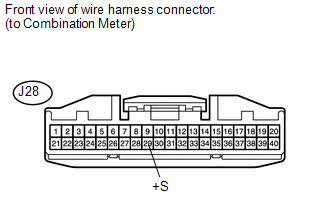
CHECK HARNESS AND CONNECTOR (COMBINATION METER - ECM) |
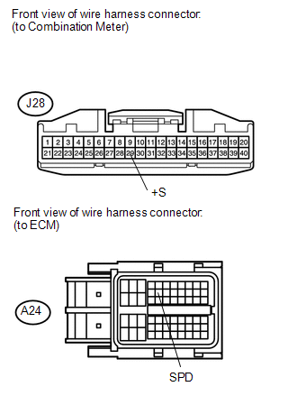 (a) Disconnect the combination meter connector.
(b) Disconnect the ECM connector. (c) Measure the resistance according to the value(s) in the table below.
Standard Resistance: |
Tester Connection | Condition |
Specified Condition | |
J28-29 (+S) - A24-13 (SPD) |
Always | Below 1 Ω | |
J28-29 (+S) or A24-13 (SPD) - Body ground |
Always | 10 kΩ or higher |
HINT: If
the wire has a short, check the speed signal circuit in other systems
related to the vehicle speed signal (e.g. the tire pressure warning
system, audio system, etc.).
| NG | |
REPAIR OR REPLACE HARNESS OR CONNECTOR (OTHER SYSTEMS RELATED TO SPEED SIGNAL) |
|
OK | |
| |
| 4. |
INSPECT COMBINATION METER ASSEMBLY (+S VOLTAGE) |
 (a) Disconnect the combination meter connector.
(b) Turn the ignition switch to ON. (c) Measure the voltage according to the value(s) in the table below.
Standard Voltage: |
Tester Connection | Switch Condition |
Specified Condition | |
J28-29 (+S) - Body ground |
Ignition switch ON | 4.5 to 5.5 V |
HINT: A voltage of 5 or 12 V is output from each ECU and then input to the combination meter assembly.
| NG |
| REPLACE ECM |
|
OK | |
| |
| 5. |
INSPECT COMBINATION METER ASSEMBLY (SPD SIGNAL OUTPUT WAVEFORM) |
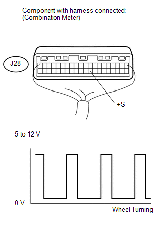 (a) Move the shift lever to N.
(b) Jack up the vehicle. (c) Turn the ignition switch to ON. (d) Measure the voltage according to the value(s) in the table below.
Standard Voltage: |
Tester Connection | Switch Condition |
Specified Condition | |
J28-29 (+S) - Body ground |
- Ignition switch ON
- Wheel is turned slowly
| Voltage generated intermittently |
HINT:
- The output voltage should fluctuate up and down similarly to the diagram when the wheel is turned slowly.
- A voltage of 5 or 12 V is output from each ECU and then input to the combination meter assembly.
| OK |
| REPLACE ECM |
|
NG | |
| |
| 6. |
INSPECT COMBINATION METER ASSEMBLY (SPD SIGNAL INPUT WAVEFORM) |
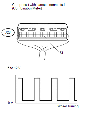 (a) Move the shift lever to the neutral position.
(b) Jack up the vehicle. (c) Turn the ignition switch to ON. (d) Measure the voltage according to the value(s) in the table below.
Standard voltage: |
Tester Connection | Switch Condition |
Specified Condition | | J28-30 (SI) - Body ground |
- Ignition switch ON
- Wheel is turned slowly
| Voltage generated intermittently |
HINT: The output voltage should fluctuate up and down, similarly to the diagram, when the wheel is turned slowly.
| OK |
| REPLACE COMBINATION METER ASSEMBLY |
|
NG | |
| |
| 7. |
CHECK HARNESS AND CONNECTOR (COMBINATION METER - VSC ACTUATOR ASSEMBLY) |
(a) Disconnect the combination meter connector. (b) Disconnect the skid control ECU connector.
(c) Measure the resistance according to the value(s) in the table below.
Standard resistance: |
Tester Connection | Condition |
Specified Condition | |
J28-30 (SI) - A57-3 (SP1) |
Always | Below 1 Ω | |
J28-30 (SI) or A57-3 (SP1) - Body ground |
Always | 10 kΩ or higher |
| OK |
| REPLACE VSC ACTUATOR ASSEMBLY |
| NG |
| REPAIR OR REPLACE HARNESS OR CONNECTOR | | 

