Toyota Tundra Service Manual: Installation

INSTALLATION

CAUTION / NOTICE / HINT

HINT:

Perform "Inspection After Repairs" after replacing the No. 1 or No. 2 camshaft sub-assembly or camshaft timing gear RH or camshaft timing exhaust gear RH (See page ).

PROCEDURE

1. INSTALL CAMSHAFT BEARING CAP RH

HINT:

Perform "Inspection After Repairs" after replacing the No. 1 or No. 2 camshaft sub-assembly (See page ).

(a) Apply a light coat of engine oil to the camshaft journals, camshaft housings and bearing caps.

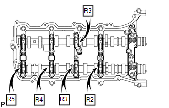
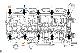
(b) Install the No. 1 and No. 2 camshafts to the camshaft housing.

(c) Confirm the marks and numbers on the camshaft bearing caps and place them in their proper positions and directions.

(d) Temporarily install the 10 bolts in the order shown in the illustration.

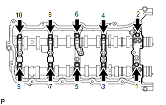
2. INSTALL CAMSHAFT HOUSING SUB-ASSEMBLY RH

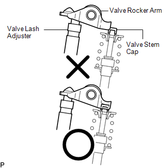
(a) Make sure that the valve rocker arms are installed as shown in the illustration.

(b) Apply seal packing in a continuous line as shown in the illustration.

Seal packing:

Toyota Genuine Seal Packing Black, Three Bond 1207B or equivalent

Standard seal diameter:

3.5 to 4.0 mm (0.138 to 0.157 in.)

NOTICE:

  • Remove any oil from the contact surface.
  • Install the camshaft housing within 3 minutes and tighten the bolts within 15 minutes after applying seal packing.

(c) Install the camshaft housing, and install the 18 bolts in the order shown in the illustration.

Torque:

for bolt A :

10 N·m {102 kgf·cm, 7 ft·lbf}

except bolt A :

30 N·m {306 kgf·cm, 22 ft·lbf}

NOTICE:

  • Do not start the engine for at least 2 hours after the installation.
  • Make sure that the knock pin of the camshaft is positioned as shown in the illustration before installing the camshaft housing.

(d) Tighten the 10 bolts in the order shown in the illustration.

Torque:

16 N·m {163 kgf·cm, 12 ft·lbf}

NOTICE:

Thoroughly wipe clean any seal packing.

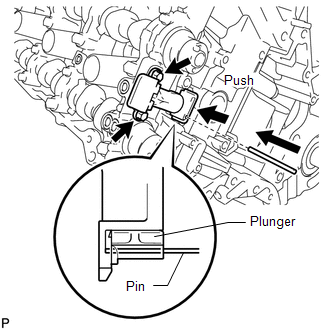
3. INSTALL NO. 2 CHAIN TENSIONER ASSEMBLY

(a) Install the chain tensioner with the 2 bolts.

Torque:

10 N·m {102 kgf·cm, 7 ft·lbf}

(b) While raising up the No. 2 chain tensioner, insert a pin of φ1.0 mm (0.0394 in.) into the hole to fix it in place.

4. INSTALL NO. 1 CHAIN SUB-ASSEMBLY RH

HINT:

Perform "Inspection After Repairs" after replacing the No. 1 or No. 2 camshaft sub-assembly or camshaft timing gear RH or camshaft timing exhaust gear RH (See page ).

(a) Align the No. 1 chain's orange mark plates with the camshaft timing gear's timing mark, and attach the chain to the gear as shown in the illustration.

(b) Align the No. 1 chain's orange mark plate with the crankshaft timing gear's timing mark, and attach the chain to the gear as shown in the illustration.

(c) Align the No. 2 chain's yellow mark plates with the timing marks of the camshaft timing gear and camshaft timing exhaust gear, and attach the No. 2 chain to the gears as shown in the illustration.

HINT:

The crankshaft timing gear and camshaft exhaust gear will be installed with the No. 1 and No. 2 chains connected to the gears.

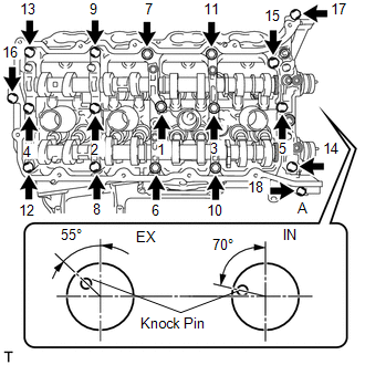
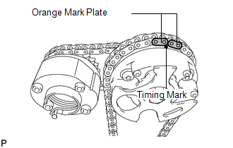
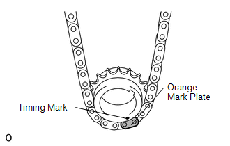
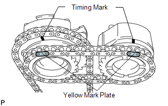
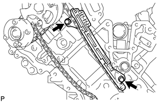
(d) Install the crankshaft timing sprocket to the crankshaft.

(e) Align and attach the knock pin of the No. 1 camshaft with the pin hole of the camshaft timing gear.

(f) Using the hexagonal portion of the No. 2 camshaft, align and attach the knock pin of the No. 2 camshaft with the pin hole of the camshaft timing exhaust gear.

(g) Remove the pin from the No. 2 chain tensioner.

5. INSTALL NO. 1 CHAIN VIBRATION DAMPER RH

(a) Install the vibration damper with the 2 bolts.

Torque:

21 N·m {214 kgf·cm, 15 ft·lbf}

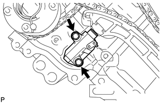
6. INSTALL NO. 1 CHAIN TENSIONER SLIPPER RH

HINT:

If you cannot install the chain tensioner slipper due to the tension of the chain, use the hexagonal portion of the camshaft to loosen the chain, and then install the chain tensioner slipper.

7. INSTALL NO. 1 CHAIN TENSIONER ASSEMBLY RH

(a) Move the stopper plate upward to release the lock, and push the plunger deep into the tensioner.

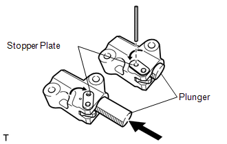
(b) Move the stopper plate downward to set the lock, and insert a hexagon wrench into the hole of the stopper plate.

(c) Install the chain tensioner with the 2 bolts.

Torque:

10 N·m {102 kgf·cm, 7 ft·lbf}

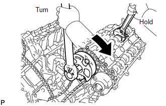
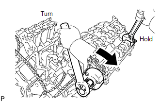
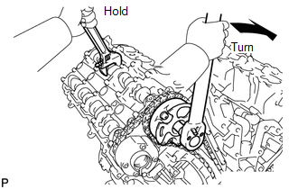
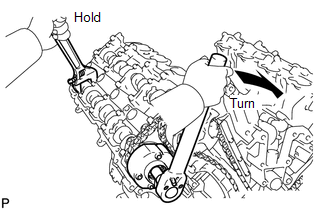
(d) Remove the hexagon wrench from the chain tensioner.

8. INSTALL NO. 1 CHAIN SUB-ASSEMBLY LH

9. INSTALL NO. 1 CHAIN TENSIONER SLIPPER LH

10. INSTALL NO. 1 CHAIN TENSIONER ASSEMBLY LH

11. INSTALL NO. 1 CHAIN VIBRATION DAMPER LH

12. TIGHTEN CAMSHAFT TIMING GEAR

(a) LH:

(1) Using a wrench to hold the hexagonal portion of the No. 3 camshaft, tighten the camshaft timing gear with the bolt.

Torque:

100 N·m {1020 kgf·cm, 74 ft·lbf}

(2) Using a wrench to hold the hexagonal portion of the No. 4 camshaft, tighten the camshaft timing exhaust gear with the bolt.

Torque:

100 N·m {1020 kgf·cm, 74 ft·lbf}

(b) RH:

(1) Using a wrench to hold the hexagonal portion of the No. 1 camshaft, tighten the camshaft timing gear with the bolt.

Torque:

100 N·m {1020 kgf·cm, 74 ft·lbf}

(2) Using a wrench to hold the hexagonal portion of the No. 2 camshaft, tighten the camshaft timing exhaust gear with the bolt.

Torque:

100 N·m {1020 kgf·cm, 74 ft·lbf}

13. CHECK NO. 1 CYLINDER TO TDC / COMPRESSION

14. INSTALL TIMING CHAIN COVER SUB-ASSEMBLY

(a) Install the timing chain cover (See page ).

15. INSPECT IGNITION TIMING

16. INSPECT ENGINE IDLE SPEED

    Components

    Removal

    See More:

    Toyota Tundra Service Manual > Audio And Visual System: D-Seat ECU Vehicle Information Reading/Writing Process Malfunction (B15F8)
    DESCRIPTION This DTC is stored when items controlled by the position control ECU and switch assembly cannot be customized via the audio and visual system vehicle customization screen. HINT: The position control ECU and switch assembly controls the front power seat control system related items that a ...

    Toyota Tundra Owners Manual

    Toyota Tundra Service Manual

    © 2024 Copyright www.ttundra.com
    0.0123