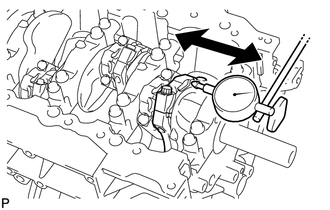
DISASSEMBLY PROCEDURE 1. INSPECT CONNECTING ROD THRUST CLEARANCE
| (a) Using a dial indicator, measure the thrust clearance while moving the connecting rod back and forth.
Standard thrust clearance: 0.15 to 0.55 mm (0.00591 to 0.0217 in.)
Maximum thrust clearance: 0.70 mm (0.0276 in.) If the thrust clearance is more than the maximum, replace one or more connecting rods as necessary.
If necessary, replace the crankshaft. | |
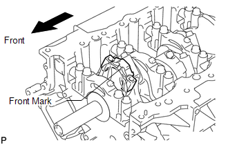
2. INSPECT CONNECTING ROD OIL CLEARANCE (a) Check that the front mark on the connecting rod and cap are aligned to ensure correct reassembly.
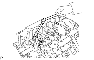
| (b) Remove the 2 connecting rod cap bolts. | |
| (c)
Using the 2 removed connecting rod cap bolts, remove the connecting rod
cap and lower bearing by wiggling the connecting rod cap right and
left. HINT: Keep the lower bearing inserted to the connecting rod cap. |
|
(d) Clean the crank pin and bearing. (e) Check the crank pin and bearing for pitting and scratches.
If the crank pin or bearing is damaged, replace the bearings. If necessary, replace the crankshaft.
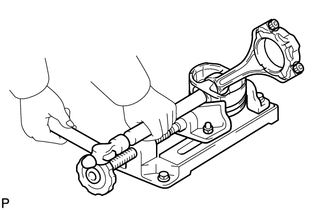
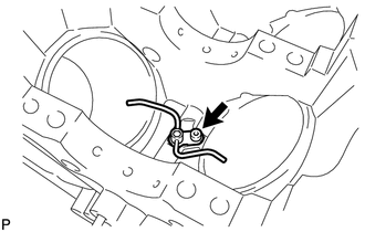
| (f) Lay a strip of Plastigage on the crank pin. | |
| (g) Check that the front mark of the connecting rod cap is facing forward. |
|
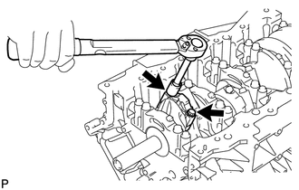
| (h) Install and alternately tighten the bolts of the connecting rod cap in several steps.
Torque: 40 N·m {408 kgf·cm, 30 ft·lbf} NOTICE: Do not turn the crankshaft. |
|
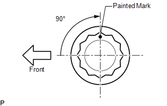
| (i) Mark the front side of each connecting rod cap bolt with paint. |
|
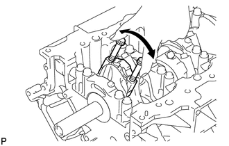
(j) Tighten the cap bolts another 90° as shown in the illustration. (k) Check that the painted marks are now at a 90° angle to the front.
NOTICE: Do not turn the crankshaft.
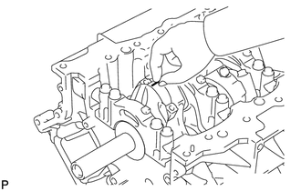
| (l) Remove the 2 connecting rod cap bolts. | |
| (m)
Using the 2 removed connecting rod cap bolts, remove the connecting rod
cap and lower bearing by wiggling the connecting rod cap right and
left. HINT: Keep the lower bearing inserted to the connecting rod cap. |
|
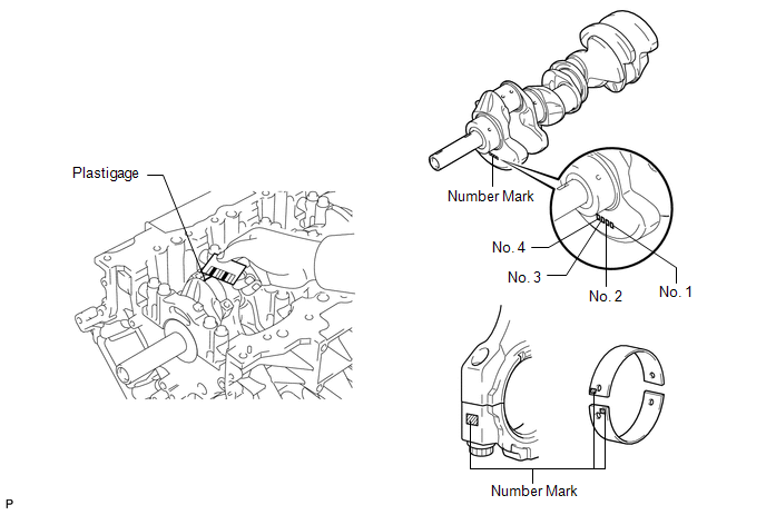 (n) Measure the Plastigage at its widest point.
Standard oil clearance: 0.025 to 0.050 mm (0.000984 to 0.00197 in.)
Maximum oil clearance: 0.070 mm (0.00276 in.) If the oil clearance is more than the maximum, replace the bearings. If necessary, replace the crankshaft.
HINT:
- If replacing a bearing, replace it with one that has the same number as
its respective connecting rod cap. Each bearing's standard thickness is
indicated by a 1, 2, 3 or 4 mark on its surface.
- Select the correct bearing by adding together the number marks imprinted on the connecting rod big end and crankshaft.
Standard Bearing Chart: |
Item | Number Mark | |
Connecting rod |
1 | 2 |
1 | 2 |
3 | 2 |
3 | 4 |
3 | 4 | |
Crankshaft | 1 |
2 | 1 |
3 | 2 |
1 | 3 |
2 | 1 |
3 | 2 |
3 | | Use bearing |
2 | 3 |
4 | 5 |
6 | 7 |
EXAMPLE: Connecting rod "1" + Crankshaft "2" = 3 (Use bearing "3")
Standard Sized Bearing Center Wall Thickness: |
Number Mark | Specified Condition | |
2 | 1.489 to 1.492 mm (0.0586 to 0.0587 in.) | |
3 | 1.492 to 1.495 mm (0.0587 to 0.0589 in.) | |
4 | 1.495 to 1.498 mm (0.0589 to 0.0590 in.) | |
5 | 1.498 to 1.501 mm (0.0590 to 0.0591 in.) | |
6 | 1.501 to 1.504 mm (0.0591 to 0.0592 in.) | |
7 | 1.504 to 1.507 mm (0.0592 to 0.0593 in.) |
Connecting Rod Big End Inside Diameter: |
Number Mark | Specified Condition | |
1 | 56.000 to 56.006 mm (2.20472 to 2.20496 in.) | |
2 | 56.006 to 56.012 mm (2.20496 to 2.20519 in.) | |
3 | 56.012 to 56.018 mm (2.20519 to 2.20543 in.) | |
4 | 56.018 to 56.024 mm (2.20543 to 2.20566 in.) |
Crankshaft Pin Diameter: |
Number Mark | Specified Condition | |
1 | 52.994 to 53.000 mm (2.08637 to 2.08661 in.) | |
2 | 52.988 to 52.994 mm (2.08614 to 2.08637 in.) | |
3 | 52.982 to 52.988 mm (2.08590 to 2.08614 in.) |
(o) Completely remove the Plastigage. (p) Perform the inspection above for each cylinder.
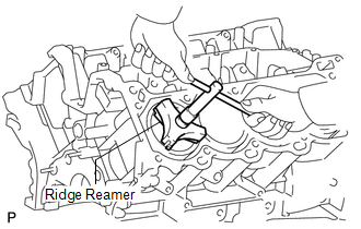
3. REMOVE PISTON AND CONNECTING ROD
| (a) Using a ridge reamer, remove all the carbon from the top of the cylinder. |
|
(b) Remove the 16 cap bolts, 8 connecting rod caps and 8 lower bearings.
(c) Push the 8 pistons and 8 connecting rods through the top of the cylinder block.
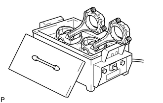
HINT: Arrange the piston and connecting rod in the correct order.
4. REMOVE CONNECTING ROD BEARING (a) Remove the connecting rod bearings from the connecting rods and connecting rod caps.
HINT: Arrange the removed parts in the correct order. 5. REMOVE PISTON RING SET
HINT: Arrange the piston rings in the correct order.
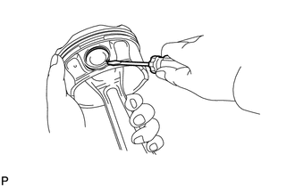
| (a) Using a piston ring expander, remove the 2 compression rings. |
|
(b) Remove the 2 side rails and oil ring expander by hand. 6. REMOVE PISTON WITH PIN SUB-ASSEMBLY
(a) Disconnect the connecting rod from the piston.
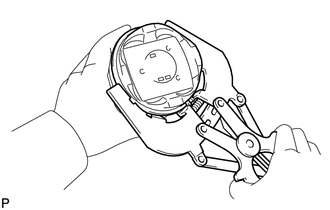
| (1) Using a small screwdriver, pry off the 2 snap rings from the piston. |
|
| (2) Gradually heat the piston to approximately 80°C (176°F). |
|
| (3) Using a brass bar and plastic-faced hammer, lightly tap out the piston pin. Then remove the connecting rod.
HINT:
- The piston and pin are a matched set.
- Arrange the pistons, pins, rings, connecting rods and bearings in the correct order.
| |
(b) Clean the piston. |
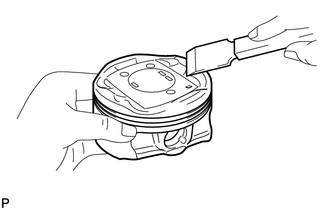
(1) Using a gasket scraper, remove the carbon from the piston top. |
|
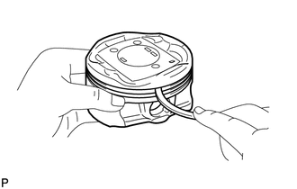
| (2) Using a groove cleaning tool or broken ring, clean the piston ring grooves. |
|
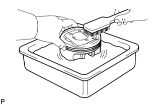
| (3) Using solvent and a brush, thoroughly clean the piston. NOTICE:
Do not use a wire brush. | |
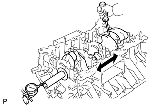
7. INSPECT CRANKSHAFT THRUST CLEARANCE
| (a) Using a dial indicator, measure the thrust clearance while prying the crankshaft back and forth with a screwdriver.
Standard thrust clearance: 0.020 to 0.220 mm (0.000787 to 0.00866 in.)
Maximum thrust clearance: 0.30 mm (0.0118 in.) If the thrust clearance is more than the maximum, replace the thrust washers as a set.
Standard thrust washer thickness: 2.44 to 2.49 mm (0.0961 to 0.0980 in.)
If necessary, replace the crankshaft. | |
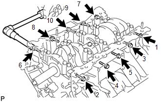
8. REMOVE CRANKSHAFT | (a)
Uniformly loosen and remove the 10 bearing cap bolts and 10 seal
washers in several steps, in the sequence shown in the illustration. |
|
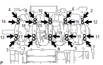
| (b) Uniformly loosen and remove the 20 bearing cap bolts in several steps, in the sequence shown in the illustration. |
|
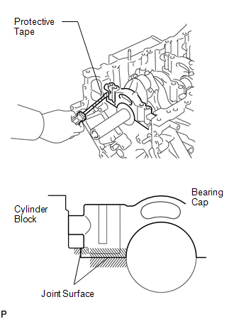
| (c) Using a screwdriver, slightly pry up the 5 main bearing caps.
HINT:
- Tape the screwdriver tip before use.
- Keep the lower bearing and crankshaft bearing cap together.
NOTICE:
- Be careful not to damage the joint surface of the cylinder block and main bearing caps.
- Pry up the left and right side of the cap little by little.
| |
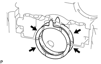
(d)
Using 2 inside position main bearing cap bolts, loosen each main
bearing cap by moving it forward and backward, and remove the 5 main
bearing caps and 2 lower thrust washers (No. 3 crankshaft bearing cap
only). HINT: Arrange the removed parts in the correct order.
(e) Remove the crankshaft. 9. REMOVE CRANKSHAFT BEARING (a) Remove the crankshaft bearings from the bearing caps and cylinder block.
HINT: Arrange the removed parts in the correct order. 10. REMOVE CRANKSHAFT THRUST WASHER SET
| (a) Remove the thrust washer set from the cylinder block and No. 3 bearing cap. |
|
11. REMOVE NO. 1 OIL NOZZLE SUB-ASSEMBLY
| (a) Using a 5 mm hexagon wrench, remove the 4 bolts and 4 oil nozzles. |
|
12. REMOVE STUD BOLT NOTICE: If the stud bolt is deformed or its threads are damaged, replace it. |