REMOVAL PROCEDURE 1. REMOVE EXHAUST MANIFOLD SUB-ASSEMBLY RH (a) Remove the exhaust manifold RH (See page 2. REMOVE CAMSHAFTS (for Bank 2) (a) Remove the camshafts (See page
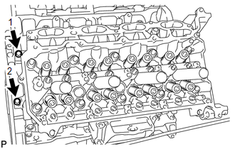
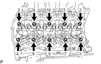
3. REMOVE NO. 1 VALVE ROCKER ARM SUB-ASSEMBLY (a) Remove the 16 valve rocker arms from the cylinder head. HINT: Arrange the removed parts in the correct order. 4. REMOVE VALVE LASH ADJUSTER ASSEMBLY (a) Remove the 16 valve lash adjusters from the cylinder head. HINT: Arrange the removed parts in the correct order. 5. REMOVE VALVE STEM CAP (a) Remove the 16 valve stem caps from the cylinder head. HINT: Arrange the removed parts in the correct order. 6. REMOVE CYLINDER HEAD SUB-ASSEMBLY RH
7. REMOVE CYLINDER HEAD GASKET RH |
Toyota Tundra Service Manual > Seat Belt: Rear Seat Inner Belt Assembly(for Crewmax)
Components COMPONENTS ILLUSTRATION Installation INSTALLATION PROCEDURE 1. INSTALL REAR NO. 1 SEAT INNER BELT ASSEMBLY LH (a) Attach the guide. (b) Tighten the bolt to install the rear No. 1 seat inner belt assembly LH. Torque: 42 N·m {428 kgf·cm, 31 ft·lbf} (c) Pull the No. 1 reclining adjuster r ...

 ).
).