Toyota Tundra Service Manual: Replacement

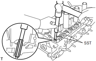
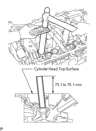
REPLACEMENT

PROCEDURE

1. REPLACE INTAKE VALVE GUIDE BUSH

(a) Heat the cylinder head to approximately 80 to 100°C (176 to 212°F).

(b) Place the cylinder head on wooden blocks.

(c) Using SST and a hammer, tap out the valve guide bush.

SST: 09201-10000

09201-01050

SST: 09950-70010

09951-07100

(d) Using a caliper gauge, measure the bush bore diameter of the cylinder head.

Standard Cylinder Head Inside Diameter:

Bush Size

Specified Condition

STD

10.285 to 10.306 mm (0.4049 to 0.4057 in.)

O/S 0.05

10.335 to 10.356 mm (0.4069 to 0.4077 in.)

(e) Select a new valve guide bush.

New Valve Guide Bush:

Bush Size

Bush Diameter

STD

10.333 to 10.344 mm (0.4068 to 0.4072 in.)

O/S 0.05

10.383 to 10.394 mm (0.4088 to 0.4092 in.)

If the bush bore diameter of the cylinder head is more than 10.306 mm (0.406 in.), machine the bush bore diameter to between 10.335 and 10.356 mm (0.4069 and 0.4077 in.).

If the bush bore diameter of the cylinder head is more than 10.356 mm (0.408 in.), replace the cylinder head.

HINT:

Standard bush length: 41.3 to 41.7 mm (1.63 to 1.64 in.)

(f) Using SST and a hammer, tap in a new guide bush to the standard protrusion height.

SST: 09201-10000

09201-01050

SST: 09950-70010

09951-07100

Standard protrusion height:

15.8 to 16.2 mm (0.622 to 0.638 in.)

(g) Using a sharp 5.5 mm reamer, ream the guide bush to obtain the standard oil clearance between the guide bush and valve stem.

Standard oil clearance:

0.025 to 0.060 mm (0.000984 to 0.00236 in.)

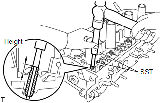
2. REPLACE EXHAUST VALVE GUIDE BUSH

(a) Heat the cylinder head to approximately 80 to 100°C (176 to 212°F).

(b) Place the cylinder head on wooden blocks.

(c) Using SST and a hammer, tap out the valve guide bush.

SST: 09201-10000

09201-01050

SST: 09950-70010

09951-07100

(d) Using a caliper gauge, measure the bush bore diameter of the cylinder head.

Standard Cylinder Head Inside Diameter:

Bush Size

Specified Condition

STD

10.285 to 10.306 mm (0.4049 to 0.4057 in.)

O/S 0.05

10.335 to 10.356 mm (0.4069 to 0.4077 in.)

(e) Select a new valve guide bush.

New Valve Guide Bush:

Bush Size

Bush Diameter

STD

10.333 to 10.344 mm (0.4068 to 0.4072 in.)

O/S 0.05

10.383 to 10.394 mm (0.4088 to 0.4092 in.)

If the bush bore diameter of the cylinder head is more than 10.306 mm (0.406 in.), machine the bush bore diameter to between 10.335 and 10.356 mm (0.4069 and 0.4077 in.).

If the bush bore diameter of the cylinder head is more than 10.356 mm (0.408 in.), replace the cylinder head.

HINT:

Standard bush length: 46.8 to 47.2 mm (1.84 to 1.86 in.)

(f) Using SST and a hammer, tap in a new guide bush to the standard protrusion height.

SST: 09201-10000

09201-01050

SST: 09950-70010

09951-07100

Standard protrusion height:

15.8 to 16.2 mm (0.622 to 0.638 in.)

(g) Using a sharp 5.5 mm reamer, ream the guide bush to obtain the standard oil clearance between the guide bush and valve stem.

Standard oil clearance:

0.030 to 0.065 mm (0.00118 to 0.00256 in.)

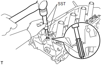
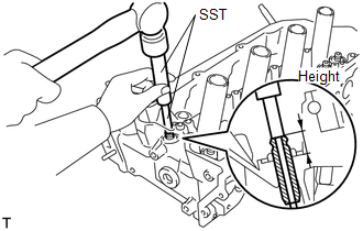
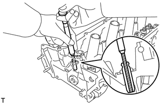
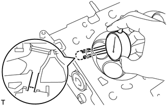
3. REPLACE SPARK PLUG TUBE

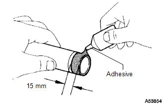
HINT:

When using a new cylinder head, the spark plug tubes must be replaced.

(a) Remove the spark plug tube.

(b) Apply adhesive to the end of a new spark plug tube.

Adhesive:

Toyota Genuine Adhesive 1324, Three Bond 1324 or equivalent.

Standard seal diameter:

15 mm (0.591 in.)

NOTICE:

  • Install the spark plug tube within 3 minutes after applying adhesive.
  • Be careful not to deform the spark plug tube.
  • Be careful not to expose the seal to coolant for at least 1 hour after installing it.

(c) Using a wooden block and hammer, tap in the spark plug tube to the specified protrusion height.

Standard protrusion height:

75.1 to 76.1 mm (2.96 to 3.00 in.)

NOTICE:

To avoid tapping in the spark plug tube too far, measure the protrusion height while tapping it.

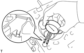
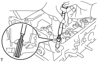
4. REPLACE RING PIN

NOTICE:

It is not necessary to remove the ring pin unless it is being replaced.

(a) Remove the ring pins.

(b) Using a plastic-faced hammer, tap in new ring pins to the cylinder head.
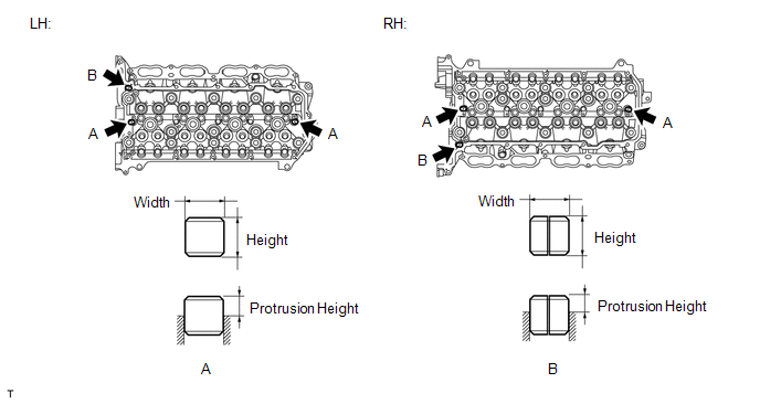
Standard Ring Pin:

Item

Height

Width

Protrusion

Ring pin A

11 mm (0.433 in.)

11 mm (0.433 in.)

5.5 to 6.5 mm (0.217 to 0.256 in.)

Ring pin B

10 mm (0.394 in.)

11 mm (0.433 in.)

3.5 to 6.5 mm (0.138 to 0.256 in.)

    Repair

    Drive Belt

    See More:

    Toyota Tundra Service Manual > 1ur-fe Engine Control: Mass Air Flow Meter
    ComponentsCOMPONENTS ILLUSTRATION InspectionINSPECTION PROCEDURE 1. INSPECT MASS AIR FLOW METER (a) Check the output voltage. (1) Apply battery voltage across terminals 1 (+B) and 2 (E2G). NOTICE: While using the battery during inspection, do not bring the positive and negative tester probes too cl ...

    Toyota Tundra Owners Manual

    Toyota Tundra Service Manual

    © 2024 Copyright www.ttundra.com
    0.0095