DISASSEMBLY PROCEDURE 1. REMOVE OIL FILTER ELEMENT 2. REMOVE OIL FILTER BRACKET 3. REMOVE CRANKSHAFT PULLEY
4. REMOVE OIL FILLER CAP SUB-ASSEMBLY 5. REMOVE OIL FILLER CAP HOUSING
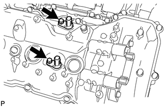
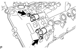
6. REMOVE SPARK PLUG (a) Using a 16 mm plug wrench, remove the 8 spark plugs. 7. REMOVE VVT SENSOR
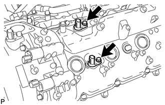
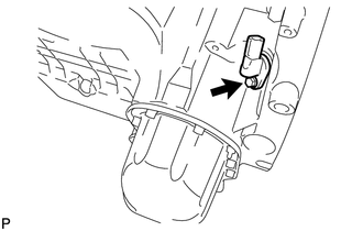
8. REMOVE CAMSHAFT POSITION SENSOR
9. REMOVE CRANKSHAFT POSITION SENSOR PROTECTOR 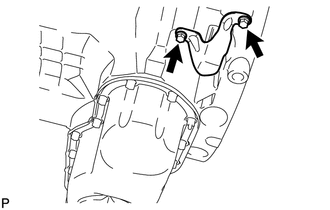 (a) Remove the 2 bolts and sensor protector. 10. REMOVE CRANKSHAFT POSITION SENSOR
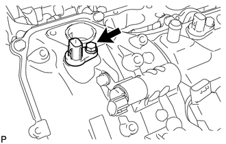
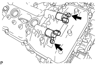
11. REMOVE CAMSHAFT OIL CONTROL VALVE ASSEMBLY
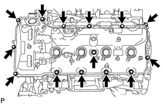
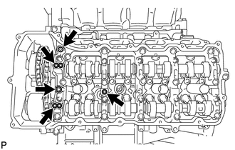
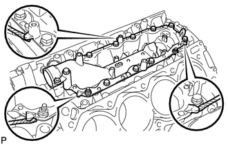
12. REMOVE CYLINDER HEAD COVER SUB-ASSEMBLY LH
13. REMOVE CYLINDER HEAD COVER SUB-ASSEMBLY RH
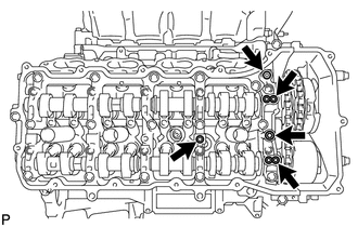
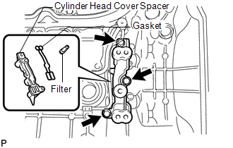
14. REMOVE OIL CONTROL VALVE FILTER 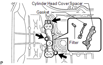 (a) LH: Remove the 3 bolts, cylinder head cover spacer, gasket and valve filter.
15. REMOVE SPARK PLUG TUBE GASKET 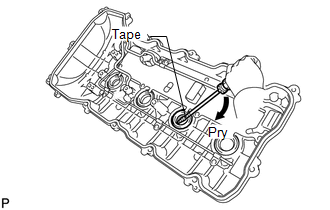 (a) Bend the 4 ventilation baffle plate claws on the cylinder head cover to an angle of 90° or more. (b) Using a screwdriver, pry out the gaskets. NOTICE: Be careful not to damage the cylinder head cover. HINT:
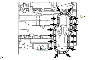
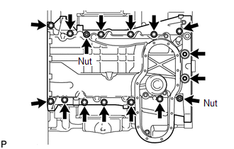
16. REMOVE WATER PUMP ASSEMBLY 17. REMOVE TIMING CHAIN COVER SUB-ASSEMBLY
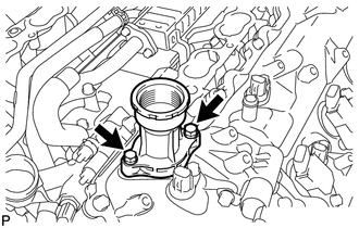
18. REMOVE WATER INLET PIPE
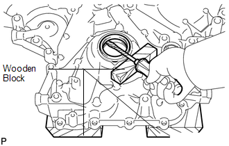
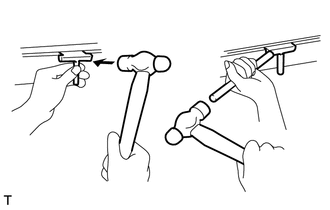
19. REMOVE FRONT CRANKSHAFT OIL SEAL (a) Place the timing chain cover on wooden blocks.
(c) Using a screwdriver and wooden block, pry out the oil seal. NOTICE: Do not damage the surface of the oil seal press fit hole. HINT: Tape the screwdriver tip before use. 20. SET NO. 1 CYLINDER TO TDC / COMPRESSION (a) Temporarily install the pulley set bolt. (b) Rotate the crankshaft clockwise so that the timing marks on the crankshaft timing gear and camshaft timing gears are as shown in the illustration. HINT: If the timing marks do not align, rotate the crankshaft clockwise again and align the timing marks. 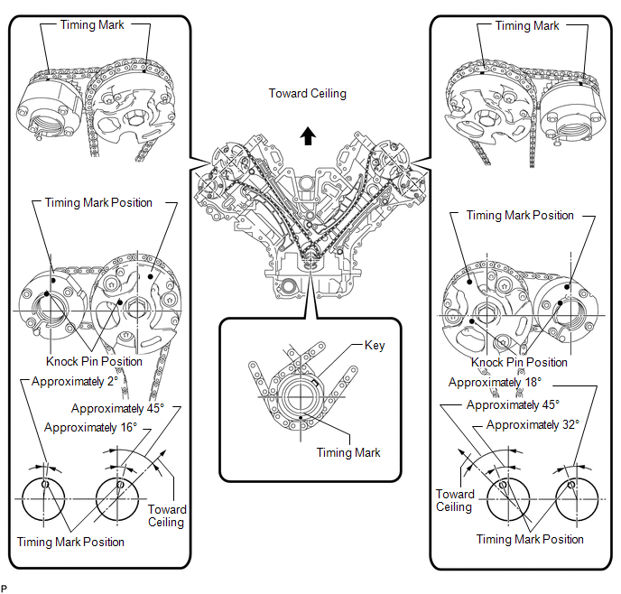 21. REMOVE NO. 1 CHAIN TENSIONER ASSEMBLY LH 22. REMOVE NO. 1 CHAIN TENSIONER SLIPPER LH 23. REMOVE NO. 1 CHAIN VIBRATION DAMPER LH 24. REMOVE NO. 1 CHAIN SUB-ASSEMBLY LH 25. REMOVE NO. 3 CHAIN TENSIONER ASSEMBLY 26. REMOVE NO. 1 CHAIN TENSIONER ASSEMBLY RH 27. REMOVE NO. 1 CHAIN TENSIONER SLIPPER RH 28. REMOVE NO. 1 CHAIN VIBRATION DAMPER RH 29. REMOVE NO. 1 CHAIN SUB-ASSEMBLY RH 30. REMOVE NO. 2 CHAIN TENSIONER ASSEMBLY 31. REMOVE CRANKSHAFT TIMING GEAR KEY  (a) Using a screwdriver, remove the 2 timing gear keys from the crankshaft. 32. REMOVE CAMSHAFT BEARING CAP LH 33. REMOVE CAMSHAFT HOUSING SUB-ASSEMBLY LH
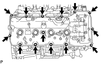
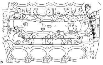
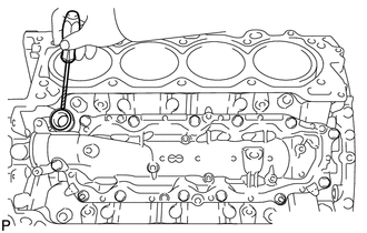
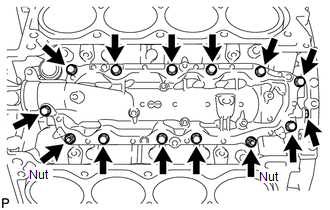
34. REMOVE CAMSHAFT BEARING CAP RH 35. REMOVE CAMSHAFT HOUSING SUB-ASSEMBLY RH 36. REMOVE VALVE ROCKER ARM SUB-ASSEMBLY (a) Remove the 32 valve rocker arms from the cylinder head. HINT: Arrange the removed parts in the correct order. 37. REMOVE VALVE LASH ADJUSTER ASSEMBLY (a) Remove the 32 valve lash adjusters from the cylinder head. HINT: Arrange the removed parts in the correct order. 38. REMOVE VALVE STEM CAP (a) Remove the 32 valve stem caps from the cylinder head. HINT: Arrange the removed parts in the correct order. 39. REMOVE CYLINDER HEAD SUB-ASSEMBLY LH 40. REMOVE CYLINDER HEAD SUB-ASSEMBLY RH 41. REMOVE CYLINDER HEAD GASKET LH 42. REMOVE CYLINDER HEAD GASKET RH 43. REMOVE CYLINDER BLOCK WATER JACKET SPACER 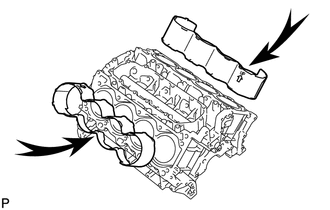 (a) Remove the 2 water jacket spacers from the cylinder head. NOTICE: Be sure to remove the water jacket spacers. If not, they may fall and become damaged when the cylinder block is inverted. 44. REMOVE OIL RETURN PIPE GASKET
45. REMOVE VENTILATION PIPE GASKET
46. REMOVE NO. 1 HEAT EXCHANGER COVER
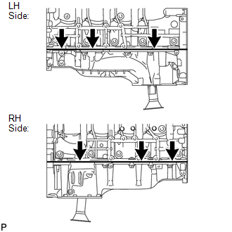
47. REMOVE NO. 2 OIL PAN SUB-ASSEMBLY
48. REMOVE NO. 1 OIL PAN SUB-ASSEMBLY
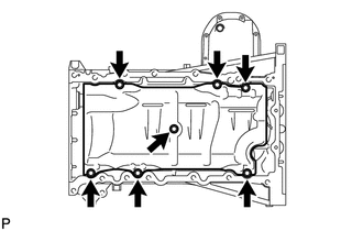
49. REMOVE NO. 1 OIL PAN BAFFLE PLATE
50. REMOVE OIL STRAINER SUB-ASSEMBLY
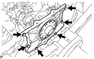
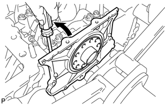
51. REMOVE ENGINE REAR OIL SEAL RETAINER
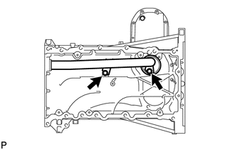
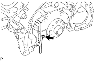
52. REMOVE OIL DRAIN PIPE SUB-ASSEMBLY
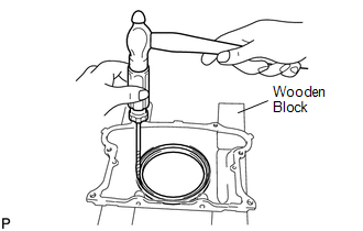
(b) Remove the O-ring. 53. REMOVE REAR CRANKSHAFT OIL SEAL
(b) Using a screwdriver and hammer, tap out the oil seal. 54. REMOVE RING PIN NOTICE: It is not necessary to remove the ring pin unless it is being replaced. 55. REMOVE STUD BOLT NOTICE: If the stud bolt is deformed or its threads are damaged, replace it. |
Toyota Tundra Service Manual > Roof Headlining(for Double Cab): Components
COMPONENTS ILLUSTRATION *1 COWL SIDE TRIM BOARD LH *2 COWL SIDE TRIM BOARD RH *3 FRONT DOOR OPENING TRIM WEATHERSTRIP LH *4 FRONT DOOR OPENING TRIM WEATHERSTRIP RH *5 FRONT DOOR SCUFF PLATE LH *6 FRONT DOOR SCUFF PLATE RH *7 REAR DOOR OPENING TRIM WEATHERSTRIP LH *8 REAR DOOR OPENING TRIM WEATHERSTR ...