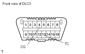
ON-VEHICLE INSPECTION PROCEDURE 1. INSPECT IGNITION TIMING (a) Warm up and stop the engine. (1) Allow the engine to warm up to a normal operating temperature. (b) When using the Techstream: (1) Connect the Techstream to the DLC3. (2) Start the engine and idle it. (3) Turn the Techstream main switch ON. (4) Enter the following menus: Powertrain / Engine and ECT / Data List / Primary / IGN Advance. HINT: Refer to the Techstream operator's manual for further details. Standard ignition timing: 7 to 24° BTDC @ idle (transmission in neutral and A/C switch OFF) (5) Disconnect the Techstream from the DLC3. (c) When not using the Techstream: 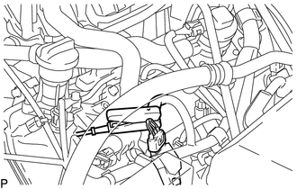 (1) Connect the tester probe of a timing light to the wire of the ignition coil connector for the No. 1 cylinder. NOTICE: Use a timing light that detects primary signals.
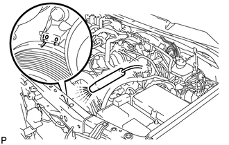
(4) Remove SST from the DLC3. (5) Check the ignition timing. Standard ignition timing: 7 to 24° BTDC @ idle (transmission in neutral and A/C switch OFF) (6) Disconnect the timing light from the engine. 2. INSPECT ENGINE IDLE SPEED (a) Warm up and stop the engine. (1) Allow the engine to warm up to a normal operating temperature. (b) When using the Techstream: (1) Connect the Techstream to the DLC3. NOTICE: Switch off all accessories and the A/C before connecting the Techstream. (2) Race the engine at 2500 rpm for approximately 90 seconds. (3) Turn the Techstream main switch ON. (4) Enter the following menus: Powertrain / Engine and ECT / Data List / Primary / Engine Speed. Standard idle speed: 650 to 750 rpm (transmission in neutral and A/C switch OFF) HINT: Refer to the Techstream operator's manual for further details. If the idle speed is not as specified, check the air intake system. (5) Disconnect the Techstream from the DLC3.
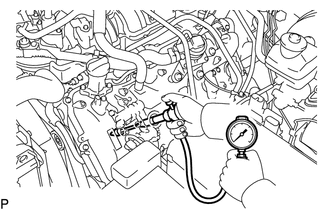
3. INSPECT COMPRESSION (a) Warm up and stop the engine. (1) Allow the engine to warm up to a normal operating temperature. (b) Remove the V-bank cover. (c) Remove the air cleaner hose assembly. (d) Remove the air cleaner cap.
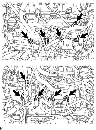
(f) Remove the 8 bolts and 8 ignition coils. (g) Remove the 8 spark plugs.
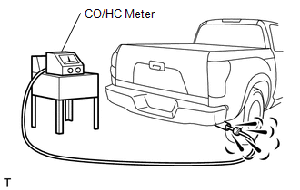
(i) Install the 8 spark plugs. (j) Install the 8 ignition coils with the 8 bolts. (k) Connect the 2 injector connectors and 8 ignition coil connectors. (l) Install the air cleaner cap. (m) Install the air cleaner hose. (n) Install the V-bank cover. 4. INSPECT CO/HC HINT: This check is used only to determine whether or not the idle CO/ HC complies with regulations. (a) Start the engine. (b) Keep the engine speed at 2500 rpm for approximately 180 seconds.
(d) Immediately check CO/HC concentration at idle and/or 2500 rpm. HINT: When performing the 2 mode (2500 rpm and idle) test, follow the measurement order prescribed by the applicable local regulations. (e) If the CO/HC concentration does not comply with the regulations, troubleshoot in the order given below. (1) Check the A/F sensor operation (See page (2) See the table below for possible causes, and then inspect and correct the applicable causes if necessary.
|
Toyota Tundra Service Manual > Lane Departure Alert System: Data List / Active Test
DATA LIST / ACTIVE TEST DATA LIST HINT: Using the Techstream to read the Data List allows the values or states of switches, sensors, actuators and other items to be read without removing any parts. This non-intrusive inspection can be very useful because intermittent conditions or signals may be dis ...

 ) and heated oxygen sensor operation (See page

