Components COMPONENTS ILLUSTRATION 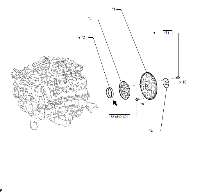
Installation INSTALLATION PROCEDURE 1. INSTALL REAR CRANKSHAFT OIL SEAL (a) Apply MP grease to the lip of a new oil seal.
2. INSTALL DRIVE PLATE AND RING GEAR SUB-ASSEMBLY
3. INSTALL AUTOMATIC TRANSMISSION ASSEMBLY (a) for 2WD: Refer to the following procedures (See page
(b) for 4WD: Refer to the following procedures (See page
4. CONNECT CABLE TO NEGATIVE BATTERY TERMINAL Removal REMOVAL PROCEDURE 1. PRECAUTION NOTICE: After
turning the ignition switch off, waiting time may be required before
disconnecting the cable from the battery terminal. Therefore, make sure
to read the disconnecting the cable from the battery terminal notice
before proceeding with work (See page 2. DISCONNECT CABLE FROM NEGATIVE BATTERY TERMINAL 3. REMOVE AUTOMATIC TRANSMISSION ASSEMBLY (a) for 2WD: Refer to the following procedures (See page
(b) for 4WD: Refer to the following procedures (See page
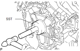
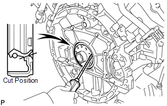
4. REMOVE DRIVE PLATE AND RING GEAR SUB-ASSEMBLY 5. REMOVE REAR CRANKSHAFT OIL SEAL (a) Using a knife, cut off the lip of the oil seal.
|
Toyota Tundra Service Manual > Sfi System: Camshaft Position "B" Actuator Circuit / Open (Bank 1) (P0013,P0023)
DESCRIPTION This DTC is designed to detect opens or shorts in the camshaft oil control valve (OCV) circuit. If the OCV's duty-cycle is excessively high or low while the engine is running, the ECM will illuminate the MIL and store the DTC. The VVT (variable valve timing) system adjusts the intake and ...