REMOVAL PROCEDURE 1. REMOVE FRONT FENDER APRON SEAL RH (a) Remove the 6 clips and fender apron seal. 2. REMOVE FRONT FENDER APRON SEAL REAR RH (a) Remove the 5 clips and fender apron seal. 3. REMOVE FRONT FENDER APRON SEAL LH (a) Remove the 6 clips and fender apron seal. 4. REMOVE FRONT FENDER APRON SEAL REAR LH (a) Remove the 5 clips and fender apron seal. 5. REMOVE INTAKE MANIFOLD (See page 6. REMOVE GENERATOR ASSEMBLY (See page 7. DISCONNECT COOLER COMPRESSOR ASSEMBLY Click here 8. REMOVE ENGINE OIL LEVEL DIPSTICK GUIDE (a) Remove the dipstick.
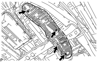
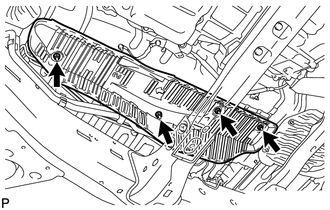
(c) Remove the O-ring from dipstick guide. 9. REMOVE EXHAUST PIPE ASSEMBLY (See page 10. REMOVE FRONT PROPELLER SHAFT ASSEMBLY (for 4WD) (See page 11. REMOVE FRONT NO. 4 FLOOR HEAT INSULATOR
12. REMOVE FRONT NO. 3 FLOOR HEAT INSULATOR
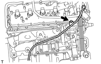
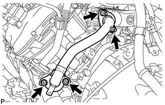
13. REMOVE NO. 1 EGR PIPE SUB-ASSEMBLY
(b) Remove the 2 gaskets. 14. REMOVE NO. 2 EXHAUST MANIFOLD HEAT INSULATOR
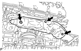
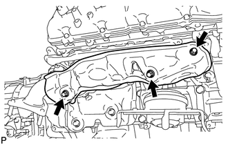
15. REMOVE EXHAUST MANIFOLD SUB-ASSEMBLY LH
16. REMOVE NO. 1 EXHAUST MANIFOLD HEAT INSULATOR
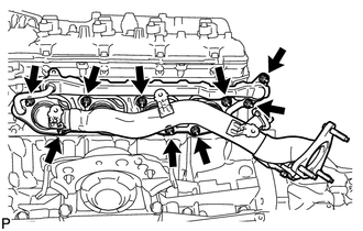
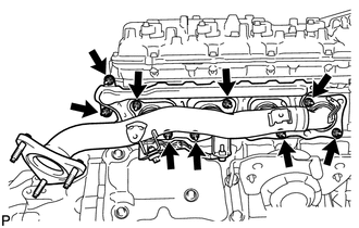
17. REMOVE EXHAUST MANIFOLD SUB-ASSEMBLY RH
|
Toyota Tundra Service Manual > Sfi System: Check Mode Procedure
CHECK MODE PROCEDURE HINT: Compared to normal mode, check mode is more sensitive to malfunctions. Therefore, check mode can detect the malfunctions that cannot be detected in normal mode. NOTICE: All the stored DTCs and freeze frame data are cleared if: 1) the ECM is changed from normal mode to chec ...

 )
)