REASSEMBLY PROCEDURE 1. INSTALL NO. 1 MONOLITHIC CONVERTER PROTECTOR (for Bank 2) (a) Install the 4 No. 1 converter protector stays to the front exhaust pipe assembly. (b) Install the lower No. 1 monolithic converter protector and upper No. 1 monolithic converter protector with the 4 bolts and 4 nuts. Torque: 11 N·m {107 kgf·cm, 8 ft·lbf} HINT: Install the No. 1 monolithic converter protector within the angle range specified in the illustration. 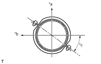 Text in Illustration Text in Illustration
2. INSTALL MONOLITHIC CONVERTER PROTECTOR (for Bank 2) (a) Install the 2 No. 1 converter protector stays and 2 No. 2 converter protector stays to the front exhaust pipe assembly. (b) Install the lower monolithic converter protector and upper monolithic converter protector with the 4 bolts and 4 nuts. Torque: 11 N·m {107 kgf·cm, 8 ft·lbf} HINT: Install the monolithic converter protector within the angle range specified in the illustration. 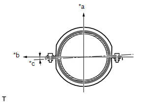 Text in Illustration Text in Illustration
3. INSTALL NO. 1 MONOLITHIC CONVERTER PROTECTOR (for Bank 1) (a) Install the 4 No. 1 converter protector stays to the front No. 2 exhaust pipe assembly. (b) Install the lower No. 1 monolithic converter protector and upper No. 1 monolithic converter protector with the 4 bolts and 4 nuts. Torque: 11 N·m {107 kgf·cm, 8 ft·lbf} HINT: Install the No. 1 monolithic converter protector within the angle range specified in the illustration. 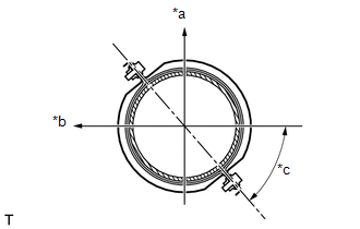 Text in Illustration Text in Illustration
4. INSTALL MONOLITHIC CONVERTER PROTECTOR (for Bank 1) (a) Install the 2 No. 1 converter protector stays and 2 No. 2 converter protector stays to the front No. 2 exhaust pipe assembly. (b) Install the lower monolithic converter protector and upper monolithic converter protector with the 4 bolts and 4 nuts. Torque: 11 N·m {107 kgf·cm, 8 ft·lbf} HINT: Install the monolithic converter protector within the angle range specified in the illustration. 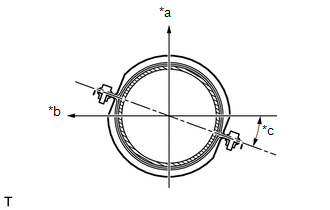 Text in Illustration Text in Illustration
|
Toyota Tundra Service Manual > Tire Pressure Warning System: Terminals Of Ecu
TERMINALS OF ECU CHECK TIRE PRESSURE WARNING ECU AND RECEIVER (a) Disconnect the P21 tire pressure warning ECU and receiver connector and measure the voltage or resistance on the wire harness side. *a Front view of wire harness connector (to Tire Pressure Warning ECU and Receiver) Terminal No. (Symb ...


