INSTALLATION CAUTION / NOTICE / HINT HINT: Perform "Inspection After Repairs" after replacing the fuel injector (See page
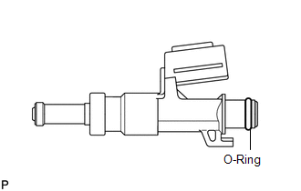
PROCEDURE 1. INSTALL FUEL INJECTOR ASSEMBLY HINT: Perform "Inspection After Repairs" after replacing the fuel injector (See page
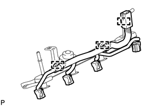
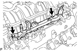
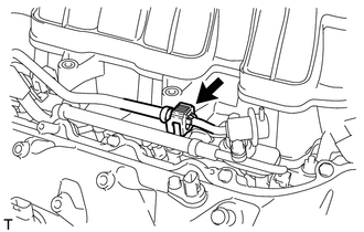
2. INSTALL FUEL DELIVERY PIPE SUB-ASSEMBLY LH
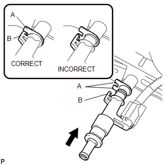
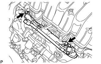
(b) Install the fuel delivery pipe sub-assembly LH (with injectors) to the cylinder head sub-assembly LH. (c) Install the 2 bolts. Torque: 21 N·m {214 kgf·cm, 15 ft·lbf} 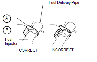 NOTICE: Make sure that the part of the fuel injector labeled B is between the parts of the fuel delivery pipe labeled A. (d) Connect the No. 7 wire harness connector. 3. INSTALL FUEL DELIVERY PIPE SUB-ASSEMBLY RH
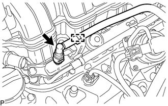
(b) Install the fuel delivery pipe sub-assembly RH (with injectors) to the cylinder head sub-assembly RH. (c) Install the 2 bolts. Torque: 21 N·m {214 kgf·cm, 15 ft·lbf}  NOTICE: Make sure that the part of the fuel injector labeled B is between the parts of the fuel delivery pipe labeled A. (d) Connect the No. 6 wire harness connector. 4. CONNECT NO. 1 FUEL PIPE SUB-ASSEMBLY
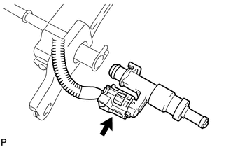
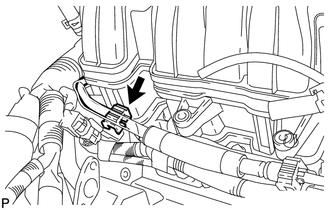
(b) Attach the clamp. 5. CONNECT FUEL TUBE SUB-ASSEMBLY
6. CONNECT NO. 2 FUEL TUBE SUB-ASSEMBLY
7. INSTALL EGR VALVE BRACKET (See page 8. CONNECT CABLE TO NEGATIVE BATTERY TERMINAL 9. CHECK FOR FUEL LEAK (a) Connect the Techstream to the DLC3. (b) Turn the ignition switch to ON and Techstream main switch on. NOTICE: Do not start the engine. (c) Enter the following menus: Powertrain / Engine and ECT / Active Test / Control the Fuel Pump / Speed. (d) Check that there are no fuel leaks after doing maintenance anywhere on the fuel system. |
Toyota Tundra Owners Manual > Interior features: Using the interior lights
Interior lights list Outer foot lights (if equipped) Personal/interior lights Engine switch light (if equipped) Foot well lighting (if equipped) Cargo lamp Personal/interior lights main switch "OFF" The personal/interior lights can be individually turned on or off. "DOOR" The personal/interior light ...

 ).
).