Components COMPONENTS ILLUSTRATION 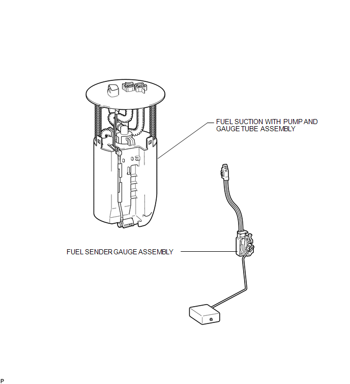 Inspection INSPECTION PROCEDURE 1. INSPECT FUEL SENDER GAUGE ASSEMBLY 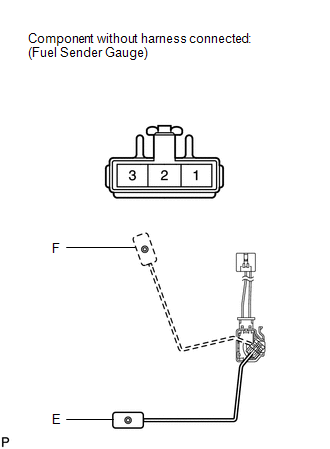 (a) Check that the float moves smoothly between F and E. (b) Measure the resistance according to the value(s) in the table below. Standard Resistance:
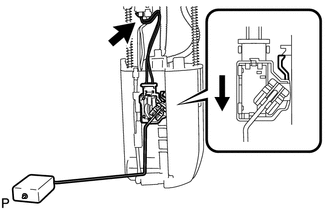
If the result is not as specified, replace the fuel sender gauge assembly. Installation INSTALLATION PROCEDURE 1. INSTALL FUEL SENDER GAUGE ASSEMBLY
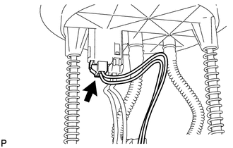
(b) Connect the fuel sender gauge connector. 2. INSTALL FUEL SUCTION WITH PUMP AND GAUGE TUBE ASSEMBLY (a) Install the fuel suction with pump and gauge tube (See page
Removal REMOVAL PROCEDURE 1. REMOVE FUEL SUCTION WITH PUMP AND GAUGE TUBE ASSEMBLY (a) Remove the fuel suction with pump and gauge tube (See page
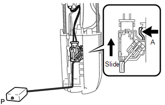
2. REMOVE FUEL SENDER GAUGE ASSEMBLY
|
Toyota Tundra Service Manual > Audio And Visual System: Portable Player cannot be Operated Using In-vehicle Device or Track Information is not Displayed on In-vehicle Device
PROCEDURE 1. CHECK USING ANOTHER "BLUETOOTH" AUDIO COMPATIBLE VEHICLE OF SAME MODEL (a) Check if track information is displayed normally on another "Bluetooth" audio compatible vehicle of the same model. OK: Track information is displayed normally. OK PROCEED TO NEXT SUSPECTED AREA SHOWN IN PROBLEM ...