INSTALLATION PROCEDURE 1. INSTALL NO. 1 FUEL TANK PROTECTOR (w/ Cover) HINT: Only perform this procedure when replacement of the No. 1 fuel tank protector is necessary. (a) Attach the 4 clamps to install a new No. 1 fuel tank protector. 2. INSTALL FUEL SUCTION WITH PUMP AND GAUGE TUBE ASSEMBLY 3. INSTALL FUEL TANK TO FILLER PIPE HOSE (a) Install the fuel tank to filler pipe hose to the fuel tank assembly. 4. INSTALL NO. 1 FUEL TANK HEAT INSULATOR (a) Install the No. 1 fuel tank heat insulator with the 4 clips and nut. Torque: 6.0 N·m {61 kgf·cm, 53 in·lbf} 5. INSTALL INLET FUEL TANK PIPE SUB-ASSEMBLY (a) Install the inlet fuel tank pipe sub-assembly with the 2 nuts. Torque: 20 N·m {204 kgf·cm, 15 ft·lbf} 6. INSTALL FUEL TANK ASSEMBLY (a) Set the fuel tank assembly on a transmission jack and raise the fuel tank assembly. (b) Attach the wire harness clamp and connect the fuel pump and fuel sender gauge connector to the fuel tank assembly. NOTICE: Be careful not to cut the wiring. (c) w/ Cover: Attach the 3 claws to install the No. 2 fuel tank protector. (d) Raise the transmission jack. (e) Install the No. 1 fuel tank band sub-assembly and No. 2 fuel tank band sub-assembly with the 2 pins and 2 clips. (f) Connect the No. 1 fuel tank band sub-assembly and No. 2 fuel tank band sub-assembly with the 2 bolts. Torque: 40 N·m {408 kgf·cm, 30 ft·lbf} 7. CONNECT OUTLET NO. 1 CHARCOAL CANISTER HOSE 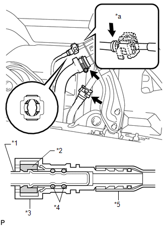 (a) Connect the outlet No. 1 charcoal canister hose to the inlet fuel tank pipe sub-assembly. Text in Illustration
(b) Attach the hose to the No. 1 breather tube support. 8. CONNECT FUEL TANK TO FILLER PIPE HOSE (a) Connect the fuel tank to filler pipe hose to the inlet fuel tank pipe sub-assembly. (b) Connect the fuel tank breather tube to the inlet fuel tank pipe sub-assembly. HINT: Push the parts together firmly until a "click" sound is heard. NOTICE:
(c) Attach the lock claws to the connector by pushing down on the cover as shown in the illustration. (d) Attach the filler pipe hose and fuel tank breather tube to the No. 1 breather tube clamp. 9. CONNECT WIRE HARNESS (a) Attach the harness clamp to the fuel tank assembly. 10. CONNECT VENT LINE HOSE (a) Connect the vent line hose and install the retainer. NOTICE:
11. CONNECT FUEL TANK RETURN TUBE 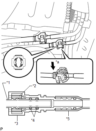 (a) Connect the fuel tank return tube. Text in Illustration
HINT: Push the parts together firmly until a "click" sound is heard. NOTICE:
(b) Attach the lock claws to the connector by pushing down on the cover as shown in the illustration. 12. CONNECT FUEL TANK MAIN TUBE SUB-ASSEMBLY 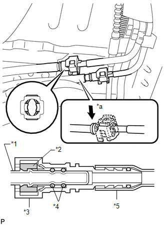 (a) Connect the fuel tank main tube sub-assembly. Text in Illustration
HINT: Push the parts together firmly until a "click" sound is heard. NOTICE:
(b) Attach the lock claws to the connector by pushing down on the cover as shown in the illustration. 13. INSTALL NO. 1 FUEL TANK PROTECTOR SUB-ASSEMBLY (for Rough Road Area Specification Vehicles) (a) Install the No. 1 fuel tank protector sub-assembly with the 2 bolts and 2 nuts. Torque: for bolt : 29 N·m {296 kgf·cm, 21 ft·lbf} for nut : 20 N·m {204 kgf·cm, 15 ft·lbf} 14. INSTALL FUEL TANK CAP 15. CONNECT CABLE TO NEGATIVE BATTERY TERMINAL 16. INSPECT FOR FUEL LEAK |
Toyota Tundra Service Manual > Lighting System: Operation Check
OPERATION CHECK AUTOMATIC LIGHT CONTROL SYSTEM OPERATION CHECK (a) Turn the ignition switch to ON. (b) Turn the light control switch to the Auto position. (c) Cover the automatic light control sensor. (d) Check that the taillights and low beam headlights turn on. (e) Uncover the automatic light cont ...


