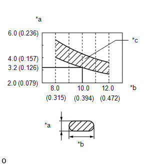
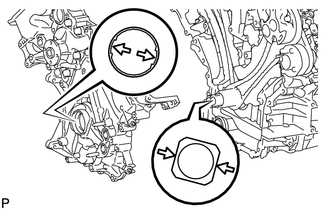
INSTALLATION PROCEDURE 1. INSTALL WATER INLET PIPE (a) Apply soapy water to 2 new O-rings and install them to the water inlet pipe. (b) Install the water inlet pipe to the No. 1 heat exchanger cover. 2. INSTALL TIMING CHAIN COVER SUB-ASSEMBLY (a) Apply a light coat of engine oil to a new oil pump gasket. (b) Install the oil pump gasket to the cylinder block. (c) Apply a light coat of engine oil to a new O-ring. (d) Install the O-ring to the oil pan sub-assembly. (e) Apply seal packing in a continuous line to the timing chain cover sub-assembly as shown in the following illustration. 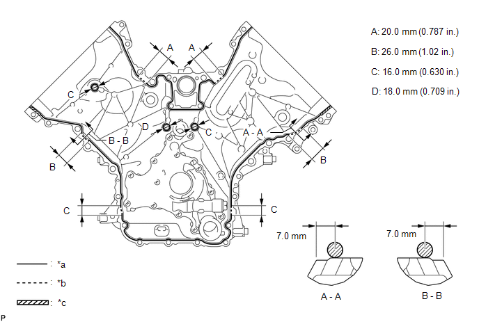 Text in Illustration Text in Illustration
Seal packing: Toyota Genuine Seal Packing Black, Three Bond 1207B or equivalent
NOTICE:
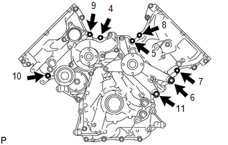
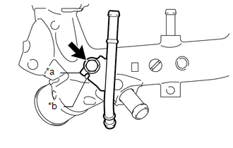
(j) Temporarily install the V-ribbed belt tensioner assembly with the bolt and 6 mm hexagon bolt to the timing chain cover sub-assembly.
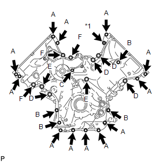
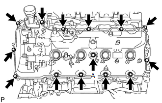
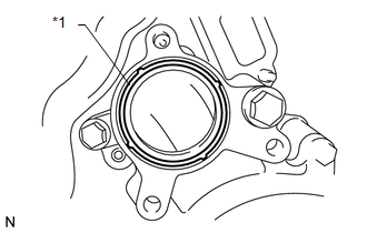
(l) Tighten the 22 bolts and nut labeled 12 to 34 in several steps in the sequence shown in the illustration. 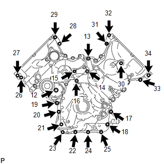 Torque: 23 N·m {235 kgf·cm, 17 ft·lbf} NOTICE: After the installation, if the seal packing has seeped out at the areas labeled A shown in the illustration, wipe it off. 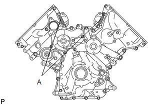 3. INSTALL FRONT CRANKSHAFT OIL SEAL 4. INSTALL CYLINDER HEAD COVER SUB-ASSEMBLY LH (a) Install 5 new gaskets to the No. 2 camshaft bearing cap and No. 3 camshaft bearing cap. (b) Install the cylinder head cover gasket LH to the cylinder head cover sub-assembly LH. NOTICE: Remove any oil from the contact surface. (c) Apply seal packing as shown in the illustration. 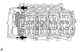 Seal packing: Toyota Genuine Seal Packing Black, Three Bond 1207B or equivalent Text in Illustration
NOTICE:
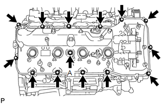
5. INSTALL CYLINDER HEAD COVER SUB-ASSEMBLY RH (a) Install 5 new gaskets to the No. 1 camshaft bearing cap and No. 3 camshaft bearing cap. (b) Install the cylinder head cover gasket RH to the cylinder head cover sub-assembly RH. NOTICE: Remove any oil from the contact surface. (c) Apply seal packing as shown in the illustration. 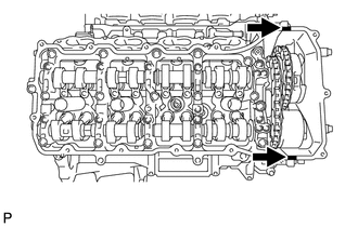 Seal packing: Toyota Genuine Seal Packing Black, Three Bond 1207B or equivalent Text in Illustration
NOTICE:
6. INSTALL IGNITION COIL ASSEMBLY (a) Install the 8 ignition coils with the 8 bolts. Torque: 10 N·m {102 kgf·cm, 7 ft·lbf} 7. CONNECT NO. 3 AIR TUBE (a) Install a new gasket to the No. 3 air tube.
(c) Install the wire harness clamp bracket with the bolt to the cylinder head cover sub-assembly RH. Torque: 8.0 N·m {82 kgf·cm, 71 in·lbf} 8. CONNECT NO. 4 AIR TUBE (a) Install a new gasket to the No. 4 air tube.
(c) Install the wire harness clamp bracket with the bolt to the cylinder head cover sub-assembly LH. Torque: 8.0 N·m {82 kgf·cm, 71 in·lbf} 9. INSTALL CRANKSHAFT PULLEY
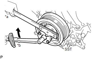
(b) Using SST, install the crankshaft pulley set bolt. SST: 09213-70011 SST: 09330-00021 Torque: 300 N·m {3059 kgf·cm, 221 ft·lbf} 10. INSTALL NO. 1 IDLER PULLEY SUB-ASSEMBLY (a) Install the No. 1 idler pulley sub-assembly to the timing chain cover sub-assembly with the bolt. Torque: 43 N·m {438 kgf·cm, 32 ft·lbf} 11. INSTALL WATER PUMP PULLEY 12. INSTALL NO. 3 WATER BY-PASS PIPE HINT: Perform this procedure only when replacement of the No. 3 water by-pass pipe is necessary.
13. INSTALL FRONT WATER BY-PASS JOINT (a) Install 2 new gaskets and the front water by-pass joint to the cylinder head with the 4 nuts. Torque: 21 N·m {214 kgf·cm, 15 ft·lbf} (b) Install the No. 2 water by-pass hose to the front water by-pass joint, and slide the clamp to secure the hose. 14. CONNECT NO. 10 WATER BY-PASS HOSE
15. CONNECT NO. 9 WATER BY-PASS HOSE (a) Connect the No. 9 water by-pass hose to the front water by-pass joint, and slide the clamp to secure the hose. 16. INSTALL WATER INLET HOUSING
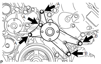
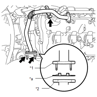
(b) Install the water inlet housing with the 3 bolts. Torque: 21 N·m {214 kgf·cm, 15 ft·lbf} 17. CONNECT NO. 5 WATER BY-PASS HOSE 18. CONNECT NO. 8 WATER BY-PASS HOSE 19. INSTALL WATER BY-PASS PIPE SUB-ASSEMBLY (a) Connect the No. 2 water by-pass hose to the water by-pass pipe sub-assembly, and slide the clamp to secure the hose. (b) Install the water by-pass pipe sub-assembly to the cylinder head cover sub-assembly RH with the 2 bolts. Torque: 10 N·m {102 kgf·cm, 7 ft·lbf} 20. INSTALL AIR TUBE SUB-ASSEMBLY RH (a) Install the air tube sub-assembly RH to the cylinder head cover sub-assembly RH with the 2 bolts. Torque: 10 N·m {102 kgf·cm, 7 ft·lbf} 21. INSTALL NO. 1 WATER BY-PASS HOSE 22. INSTALL NO. 3 ENGINE COVER 23. INSTALL NO. 4 ENGINE COVER 24. INSTALL GENERATOR ASSEMBLY 25. CONNECT VANE PUMP ASSEMBLY 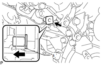 (a) Connect the vane pump assembly to the timing chain cover sub-assembly with the 2 bolts. Torque: 28 N·m {286 kgf·cm, 21 ft·lbf} Text in Illustration
HINT: Before performing the following procedures, move the spacer until the vane pump assembly can be installed. 26. INSTALL ENGINE OIL LEVEL DIPSTICK GUIDE
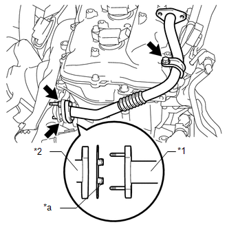
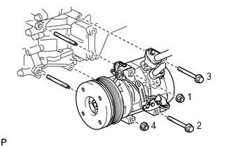
27. INSTALL OIL FILTER BRACKET (a) Apply a light coat of engine oil to 2 new O-rings. (b) Install the 2 O-rings to the timing chain cover sub-assembly. (c) Install the oil filter bracket to the timing chain cover sub-assembly with the 2 nuts and 2 bolts. Torque: 35 N·m {357 kgf·cm, 26 ft·lbf} 28. INSTALL OIL PRESSURE SENDER GAUGE ASSEMBLY 29. INSTALL OIL FILTER ELEMENT 30. CONNECT COOLER COMPRESSOR ASSEMBLY
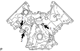
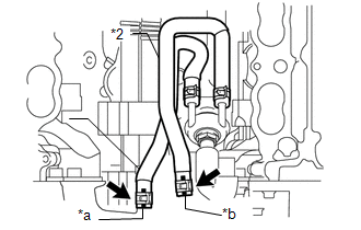
(b) Install the 2 bolts and 2 nuts. Torque: 25 N·m {250 kgf·cm, 18 ft·lbf} NOTICE: Tighten the bolts and nuts in the order shown in the illustration to connect the cooler compressor assembly. 31. CONNECT HEATER HOSE AND NO. 1 WATER BY-PASS PIPE (a) Connect the No. 1 water by-pass pipe with the 2 bolts to the cylinder head cover sub-assembly RH. Torque: 18 N·m {184 kgf·cm, 13 ft·lbf} (b) Connect the heater hose to the water by-pass pipe sub-assembly, and slide the clamp to secure the hose. 32. CONNECT NO. 3 AIR INJECTION SYSTEM HOSE (a) Connect the No. 3 air injection system hose to the air tube sub-assembly RH, and slide the clamp to secure the hose. 33. CONNECT ENGINE WIRE (a) Connect the wire harness clamp bracket to the timing chain cover sub-assembly with the bolt. Torque: 8.0 N·m {82 kgf·cm, 71 in·lbf} (b) Engine Room RH Side: (1) Connect the 9 clamps. (2) Connect the 2 air pump connectors. (3) Install the ground wire RH with the bolt. Torque: 8.0 N·m {82 kgf·cm, 71 in·lbf} (4) Connect the noise filter connector. (5) Connect the 2 VVT sensor connectors. (6) Connect the injector connector. (7) Connect the 4 ignition coil connectors. (8) Connect the 2 camshaft timing oil control valve connectors. (9) Connect the power steering oil pressure switch connector and solenoid valve connector. (10) for 4WD: Connect the clamp and junction connector. (c) Engine Room LH Side: (1) Connect the cooler compressor connector. (2) Connect the 6 clamps. (3) Connect the camshaft position sensor connector. (4) Connect the 2 camshaft timing oil control valve connectors. (5) Connect the engine coolant temperature sensor connector. (6) Install the ground wire LH with the bolt. Torque: 8.0 N·m {82 kgf·cm, 71 in·lbf} (7) Connect the noise filter connector. (8) Connect the 2 VVT sensor connectors. (9) Connect the 4 ignition coil connectors. (10) Connect the injector connector. (11) Connect the 2 wire harness clamps. (12) Connect the 4 air injection control driver connectors. (13) Connect the 2 connectors and attach the 2 clamps to the engine room junction block. (14) Install the engine room relay block cover. 34. INSTALL AIR SWITCHING VALVE ASSEMBLY (for Bank 2) 35. CONNECT NO. 1 AIR HOSE
36. INSTALL AIR SWITCHING VALVE ASSEMBLY (for Bank 1) 37. INSTALL INTAKE MANIFOLD (See page
38. INSTALL RADIATOR ASSEMBLY (See page
39. ADD ENGINE OIL
40. ADD ENGINE COOLANT 41. CONNECT CABLE TO NEGATIVE BATTERY TERMINAL 42. INSPECT FOR OIL LEAK 43. INSPECT FOR COOLANT LEAK
44. CHECK ENGINE OIL LEVEL
|
Toyota Tundra Service Manual > Rear Seat Assembly(for Crewmax Lh Side): Disassembly
DISASSEMBLY CAUTION / NOTICE / HINT CAUTION: Wear protective gloves. Sharp areas on the parts may injure your hands. PROCEDURE 1. REMOVE REAR SEAT HEADREST ASSEMBLY (a) Push the 2 lock release buttons indicated by the arrows in the illustration to release the lock, and then remove the rear seat head ...