
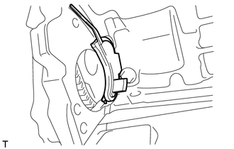
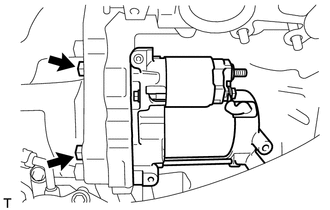
INSTALLATION PROCEDURE 1. INSTALL STARTER ASSEMBLY
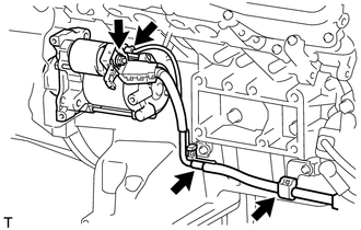
(d) Connect the starter connector. (e) Connect the 2 wire harness clamps. 2. INSTALL STARTER COVER
3. INSTALL EXHAUST MANIFOLD SUB-ASSEMBLY RH (a) Install the exhaust manifold RH (See page
4. CONNECT CABLE TO NEGATIVE BATTERY TERMINAL |
Toyota Tundra Service Manual > Front Seat Inner Belt Assembly: Removal
REMOVAL CAUTION / NOTICE / HINT HINT: Use the same procedure for the RH and LH sides. The procedure listed below is for the LH side. PROCEDURE 1. PRECAUTION NOTICE: After turning the ignition switch off, waiting time may be required before disconnecting the cable from the battery terminal. Therefore ...

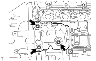
 ).
).
