DESCRIPTION The speed sensor SP2 detects the rotation speed of the transmission output shaft and sends signals to the ECM. The ECM determines the vehicle speed based on these signals. An AC voltage is generated in the speed sensor SP2 coil as the parking gear mounted on the rear planetary gear assembly rotates, and this voltage is sent to the ECM. The parking gear on the rear planetary gear is used as the timing rotor for this sensor. The gear shift point and lock-up timing are controlled by the ECM based on the signals from this vehicle speed sensor and the throttle position sensor signal.
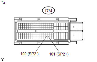
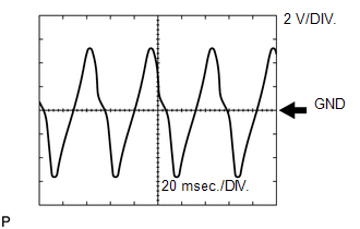
Reference: Inspect using an oscilloscope. Check the waveform of the ECM connector. Standard:
 MONITOR DESCRIPTION The output speed sensor SP2 monitors the output shaft speed. The ECM controls the gear shift point and lock-up timing based on the signals from the output speed sensor SP2 and throttle position sensor. If the ECM detects no signal from the output speed sensor SP2 even while the vehicle is moving, it will conclude that there is a malfunction of the output speed sensor SP2. The ECM will illuminate the MIL and store the DTC. MONITOR STRATEGY
TYPICAL ENABLING CONDITIONS
TYPICAL MALFUNCTION THRESHOLDS
COMPONENT OPERATING RANGE
WIRING DIAGRAM 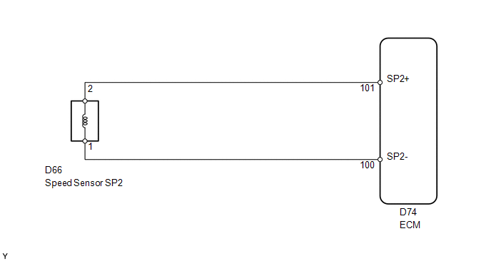 CAUTION / NOTICE / HINT NOTICE: Perform the universal trip to clear permanent DTCs (See page
1. DATA LIST HINT: Using the Techstream to read the Data List allows the values or states of switches, sensors, actuators and other items to be read without removing any parts. This non-intrusive inspection can be very useful because intermittent conditions or signals may be discovered before parts or wiring is disturbed. Reading the Data List information early in troubleshooting is one way to save diagnostic time. NOTICE: In the table below, the values listed under "Normal Condition" are reference values. Do not depend solely on these reference values when deciding whether a part is faulty or not. (a) Warm up the engine. (b) Turn the ignition switch off. (c) Connect the Techstream to the DLC3. (d) Turn the ignition switch to ON. (e) Turn the Techstream on. (f) Enter the following menus: Powertrain / Engine and ECT / Data List. (g) According to the display on the Techstream, read the Data List. Engine and ECT
HINT:
PROCEDURE
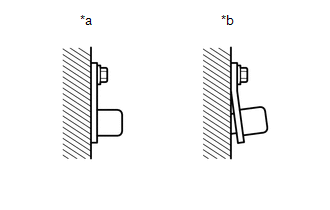
(b) Measure the resistance according to the value(s) in the table below. Standard Resistance:
(b) Measure the resistance according to the value(s) in the table below. Standard Resistance:
|
Toyota Tundra Service Manual > Theft Deterrent System: Precaution
PRECAUTION DOOR CONTROL RECEIVER EXPRESSIONS (a) The type of door control receiver used on this model differs according to the specifications of the vehicle. The expressions listed in the table below are used in this section. Part Name in Manual Actual Part Name Door control receiver Door control an ...

 ).
).