DESCRIPTION Shifting from
1st to 6th is performed in combination with the ON and OFF operation of
the shift solenoid valves SL1, SL2, S1, S2, S3, S4 and SR, which are
controlled by the ECM. If an open or short circuit occurs in the shift
solenoid valves, the ECM controls the remaining normal shift solenoid
valves to allow the vehicle to be operated safely (See page
 ). ). |
DTC Code | DTC Detection Condition |
Trouble Area | | P0748 |
The
ECM checks for an open or short in the shift solenoid valve SL1 circuit
while driving and shifting between 4th and 5th gear (1-trip detection
logic). Output signal duty equals 100%. HINT: SL1 output signal duty is less than 100% under normal conditions. |
- Open or short in shift solenoid valve SL1 circuit
- Shift solenoid valve SL1
- ECM
| MONITOR DESCRIPTION
This
DTC indicates an open or short in the shift solenoid valve SL1 circuit.
The ECM commands gear shifts by turning the shift solenoid valves
ON/OFF. When there is an open or short circuit in any shift solenoid
valve circuit, the ECM detects the problem, illuminates the MIL and
stores the DTC. Also, the ECM performs the fail-safe function and turns
the other normal shift solenoid valves ON/OFF. In case of an open or
short circuit, the ECM stops sending current to the open or
short-circuited solenoid. While driving and
shifting between 4th and 5th gears, if the ECM detects an open or short
in the shift solenoid valve SL1 circuit, the ECM determines that there
is a malfunction (See page ). MONITOR STRATEGY |
Related DTCs | P0748: Shift solenoid valve SL1/Range check | |
Required sensors/Components | Shift solenoid valve SL1 | |
Frequency of operation | Continuous | |
Duration | 1 second | | MIL operation |
Immediately | | Sequence of operation |
None | TYPICAL ENABLING CONDITIONS |
The monitor will run whenever the following DTCs are not present |
None | | Solenoid current cut status |
Not cut | | Battery voltage |
11 V or more | | Ignition switch |
ON | | Starter |
OFF | TYPICAL MALFUNCTION THRESHOLDS |
Solenoid status from solenoid driver MIC | Fail | COMPONENT OPERATING RANGE |
Output signal duty | Less than 100% | WIRING DIAGRAM
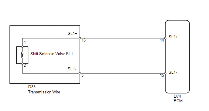 CAUTION / NOTICE / HINT
NOTICE: Perform the universal trip to clear permanent DTCs (See page
). HINT: The shift solenoid valve SL1 turns ON/OFF normally when the shift lever is in D: |
ECM gear shift command | 1st |
2nd | 3rd |
4th | 5th |
6th | | Shift solenoid valve SL1 |
OFF | OFF |
OFF | OFF |
ON | ON | PROCEDURE
| 1. |
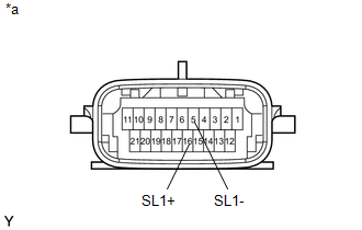
INSPECT TRANSMISSION WIRE (SHIFT SOLENOID VALVE SL1) |
| (a) Disconnect the D83 transmission wire connector. | |
(b) Measure the resistance according to the value(s) in the table below.
Standard Resistance: |
Tester Connection | Condition |
Specified Condition | |
16 (SL1+) - 5 (SL1-) |
20°C (68°F) | 5.0 to 5.6 Ω | |
16 (SL1+) - Body ground |
Always | 10 kΩ or higher | |
5 (SL1-) - Body ground |
Always | 10 kΩ or higher | Text in Illustration |
*a | Component without harness connected
(Transmission Wire) |
| NG |
 | GO TO STEP 3 |
|
OK |
 | |
| 2. |
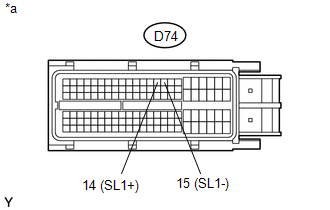
CHECK HARNESS AND CONNECTOR (TRANSMISSION WIRE - ECM) |
| (a) Disconnect the D74 ECM connector. | |
(b) Measure the resistance according to the value(s) in the table below.
Standard Resistance: |
Tester Connection | Condition |
Specified Condition | |
D74-14 (SL1+) - D74-15 (SL1-) |
20°C (68°F) | 5.0 to 5.6 Ω | |
D74-14 (SL1+) - Body ground |
Always | 10 kΩ or higher | |
D74-15 (SL1-) - Body ground |
Always | 10 kΩ or higher | Text in Illustration |
*a | Front view of wire harness connector
(to ECM) |
| OK |
| REPLACE ECM |
| NG |
| REPAIR OR REPLACE HARNESS OR CONNECTOR |
| 3. |
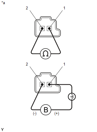
INSPECT SHIFT SOLENOID VALVE SL1 |
| (a) Remove shift solenoid valve SL1. | |
(b) Measure the resistance according to the value(s) in the table below.
Standard Resistance: |
Tester Connection | Condition |
Specified Condition | |
1 - 2 | 20°C (68°F) |
5.0 to 5.6 Ω | (c) Apply 12 V battery voltage to the shift solenoid valve and check that the valve moves and makes an operating noise.
OK: |
Measurement Condition | Specified Condition |
- Battery positive (+) with a 21 W bulb → Terminal 1
- Battery negative (-) → Terminal 2
| Valve moves and makes an operating noise | Text in Illustration |
*a | Component without harness connected
(Shift Solenoid Valve SL1) |
| OK |
| REPAIR OR REPLACE TRANSMISSION WIRE |
| NG |
| REPLACE SHIFT SOLENOID VALVE SL1 | |