|
Terminal No. (Symbol) | Wiring Color |
Terminal Description | Condition |
Specified Condition |
|
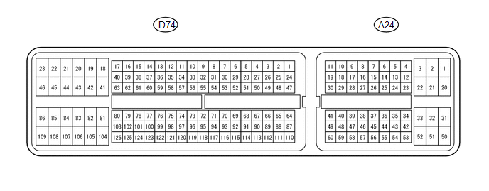
D74-120 (NSW) - D74-81 (E1) |
L - BR | PNP switch signal |
- Ignition switch ON
- Shift lever in P or N
| Below 1 V |
- Ignition switch ON
- Shift lever not in P or N
| 11 to 14 V |
|
D74-2 (P) - D74-81 (E1) |
G-B - BR | P shift position switch signal |
- Ignition switch ON
- Shift lever in P
| 11 to 14 V |
- Ignition switch ON
- Shift lever not in P
| Below 1 V |
|
D74-26 (R) - D74-81 (E1) |
L-R - BR | R shift position switch signal |
- Ignition switch ON
- Shift lever in R
| 11 to 14 V |
- Ignition switch ON
- Shift lever not in R
| Below 1 V |
|
D74-25 (N) - D74-81 (E1) |
G-W - BR | N shift position switch signal |
- Ignition switch ON
- Shift lever in N
| 11 to 14 V |
- Ignition switch ON
- Shift lever not in N
| Below 1 V |
|
D74-27 (D) - D74-81 (E1) |
G - BR | D shift position switch signal |
- Ignition switch ON
- Shift lever in D
| 11 to 14 V |
- Ignition switch ON
- Shift lever not in D
| Below 1 V |
|
A24-25 (S) - D74-81 (E1) |
Y - BR | S shift position switch signal |
- Ignition switch ON
- Shift lever in S
| 11 to 14 V |
- Ignition switch ON
- Shift lever not in S
| Below 1 V |
|
A24-38 (SFTU) - D74-81 (E1) |
G - BR | Up-shift position switch signal |
- Ignition switch ON
- Shift lever in S
| 11 to 14 V |
- Ignition switch ON
- Shift lever in "+" (up-shift)
| Below 1 V |
|
A24-27 (SFTD) - D74-81 (E1) |
BE - BR | Down-shift position switch signal |
- Ignition switch ON
- Shift lever in S
| 11 to 14 V |
- Ignition switch ON
- Shift lever in "-" (down-shift)
| Below 1 V |
|
D74-7 (S1) - D74-81 (E1) |
R - BR | S1 solenoid signal |
1st gear | Below 1 V |
|
Not in 1st gear | 11 to 14 V |
|
D74-6 (S2) - D74-81 (E1) |
W - BR | S2 solenoid signal |
1st, 2nd or 6th gear |
11 to 14 V |
| 3rd, 4th or 5th gear |
Below 1 V |
|
D74-3 (S3) - D74-81 (E1) |
G-W - BR | S3 solenoid signal |
1st, 2nd or 3rd gear |
11 to 14 V |
| 4th, 5th or 6th gear |
Below 1 V |
|
D74-5 (S4) - D74-81 (E1) |
G-R - BR | S4 solenoid signal |
5th or 6th gear | 11 to 14 V |
|
1st, 2nd, 3rd or 4th gear |
Below 1 V |
|
D74-4 (SR) - D74-81 (E1) |
G - BR | SR solenoid signal |
1st, 2nd, 3rd or 4th gear |
11 to 14 V |
| 5th or 6th gear |
Below 1 V |
|
D74-14 (SL1+) - D74-15 (SL1-) |
Y - L | SL1 solenoid signal |
5th or 6th gear | Pulse generation |
|
D74-12 (SL2+) - D74-13 (SL2-) |
G-R - L-W | SL2 solenoid signal |
Engine is idling | Pulse generation |
|
D74-9 (SLT+) - D74-8 (SLT-) |
B - G-B | SLT solenoid signal |
Engine is idling | Pulse generation |
|
D74-10 (SLU+) - D74-11 (SLU-) |
L-Y - L-R | SLU solenoid signal |
5th gear (lock-up) or 6th gear (lock-up) |
Pulse generation |
|
D74-122 (THO1) - D74-98 (E2) |
G-Y - BR | No. 1 ATF temperature sensor signal |
No. 1 ATF temperature: 115°C (239°F) or more |
Below 1.5 V |
|
D74-99 (THO2) - D74-98 (E2) |
L - BR | No. 2 ATF temperature sensor signal |
No. 2 ATF temperature: 115°C (239°F) or more |
Below 1.5 V |
|
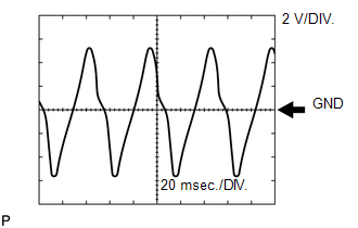
D74-101 (SP2+) - D74-100 (SP2-) |
Y - B | Speed sensor SP2 signal |
Vehicle speed 20 km/h (12 mph) |
Pulse generation (see waveform 1) |
|
D74-124 (NT+) - D74-123 (NT-) |
Y - B | Speed sensor NT signal |
Engine idling (shift lever in P or N) |
Pulse generation (see waveform 2) |
|
A24-10 (CANH) - D74-81 (E1) |
GR - BR | CAN communication line |
Ignition switch ON | Pulse generation
(see waveform 3) |
|
A24-11 (CANL) - D74-81 (E1) |
W - BR | CAN communication line |
Ignition switch ON | Pulse generation
(see waveform 4) |
 Reference
 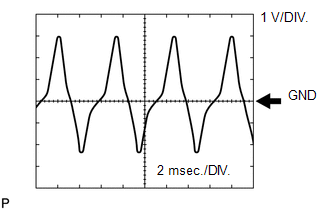 Reference
 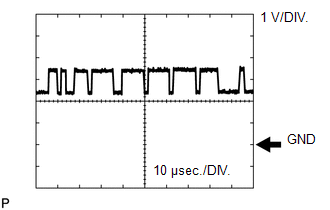 Reference
 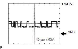 Reference

