Components COMPONENTS ILLUSTRATION 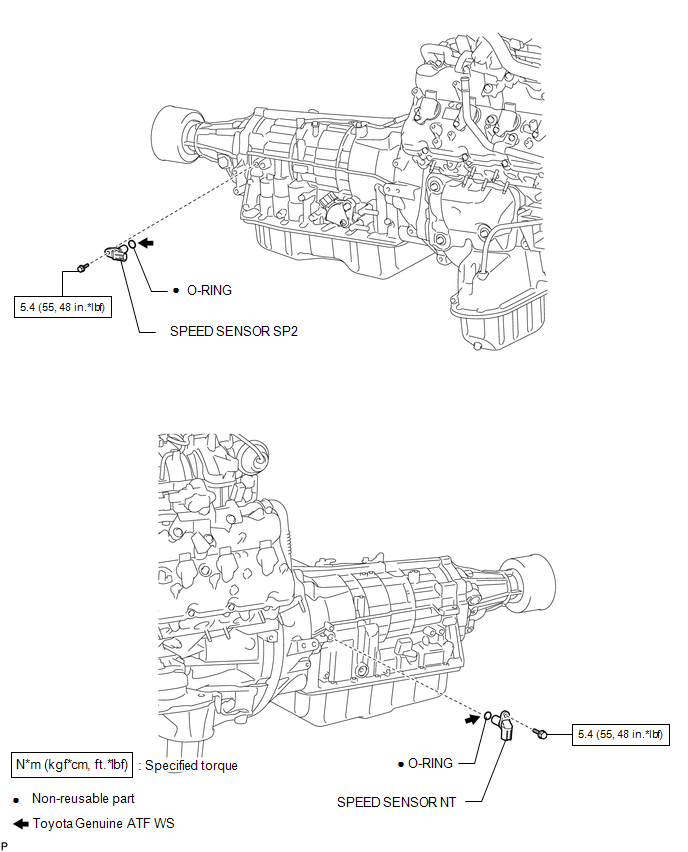 Inspection INSPECTION PROCEDURE 1. INSPECT SPEED SENSOR NT 
(a) Measure the resistance according to the value(s) in the table below. Standard Resistance:
If the result is not as specified, replace the sensor. 2. INSPECT SPEED SENSOR SP2 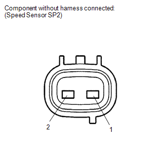
(a) Measure the resistance according to the value(s) in the table below. Standard Resistance:
If the result is not as specified, replace the sensor. Installation INSTALLATION PROCEDURE 1. INSTALL SPEED SENSOR SP2 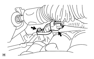
(a) Coat a new O-ring with ATF and install it to the sensor. (b) Install the sensor with the bolt. Torque: 5.4 N·m {55 kgf·cm, 48 in·lbf} (c) Connect the sensor connector. 2. INSTALL SPEED SENSOR NT 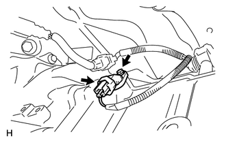
(a) Coat a new O-ring with ATF and install it to the sensor. (b) Install the sensor with the bolt. Torque: 5.4 N·m {55 kgf·cm, 48 in·lbf} (c) Connect the sensor connector. Removal REMOVAL PROCEDURE 1. REMOVE SPEED SENSOR NT  (a) Disconnect the sensor connector. (b) Remove the bolt and sensor. (c) Remove the O-ring from the sensor. 2. REMOVE SPEED SENSOR SP2  (a) Disconnect the sensor connector. (b) Remove the bolt and sensor. (c) Remove the O-ring from the sensor. |
Toyota Tundra Service Manual > Front Door(for Double Cab): Adjustment
ADJUSTMENT CAUTION / NOTICE / HINT HINT: Before adjusting the door position for vehicles equipped with side airbags and curtain shield airbags, be sure to disconnect the battery. After adjustment, inspect the SRS warning light and check for DTC (see page ). Use the same procedures for the RH side an ...


