INSTALLATION CAUTION / NOTICE / HINT HINT:
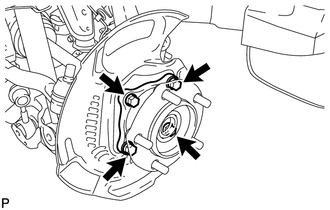
PROCEDURE 1. INSTALL FRONT AXLE HUB SUB-ASSEMBLY LH (for 2WD) (a) Apply MP grease to a new O-ring. (b) Install the O-ring to the axle hub. NOTICE: Do not damage the O-ring.
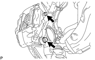
2. INSTALL FRONT AXLE HUB SUB-ASSEMBLY LH (for 4WD) (a) Apply MP grease to a new O-ring. (b) Install the O-ring to the axle hub. NOTICE: Do not damage the O-ring. (c) Connect the front drive shaft to the front axle hub. NOTICE: Be careful not to damage the front drive shaft boot.
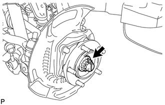
3. INSTALL FRONT AXLE HUB NUT LH (for 4WD) (a) Clean the threaded parts on the drive shaft and axle hub nut using a non-residue solvent. NOTICE:
(b) Using a 39 mm socket wrench, install the hub nut. Torque: 338 N·m {3446 kgf·cm, 249 ft·lbf}
4. INSPECT FRONT AXLE HUB (a) Inspect the front axle hub (see page
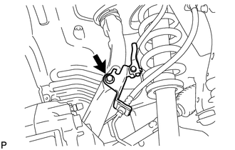
5. INSTALL FRONT AXLE HUB GREASE CAP LH (for 4WD) (a) Install the axle hub grease cap. NOTICE: Make sure to securely fit the bearing to the axle hub. 6. INSTALL FRONT DISC LH 7. CONNECT FRONT DISC BRAKE CALIPER ASSEMBLY LH
8. INSTALL FRONT WHEEL Torque: for Aluminum Wheel : 131 N·m {1336 kgf·cm, 97 ft·lbf} for steel Wheel : 209 N·m {2131 kgf·cm, 154 ft·lbf} 9. CHECK SPEED SENSOR SIGNAL (a) Check the speed sensor signal (see page |
Toyota Tundra Service Manual > Sfi System: Secondary Air Injection System Driver (P1613,P1614)
DESCRIPTION Refer to DTC P0412 (See page ). DTC No. DTC Detection Condition Trouble Area P1613 P1614 Either of following conditions (1) or (2) met: (1) All of following conditions met (1 trip detection logic): Either air pump or air switching valve not operating Diagnostic signal from Air Injection ...

 ).
).