TERMINALS OF ECU CHECK ECM (for 1UR-FE) 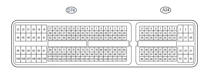 HINT: The standard voltage, resistance and waveform between each pair of the ECM terminals is shown in the table below. The appropriate conditions for checking each pair of the terminals is also indicated. The result of checks should be compared with the standard voltage, resistance and waveform for each pair of the terminals as displayed in the Specified Condition column. The illustration above can be used as a reference to identify the ECM terminal locations.
CHECK ECM (for 3UR-FE)  HINT: The standard voltage, resistance and waveform between each pair of the ECM terminals is shown in the table below. The appropriate conditions for checking each pair of the terminals is also indicated. The result of checks should be compared with the standard voltage, resistance and waveform for each pair of the terminals as displayed in the Specified Condition column. The illustration above can be used as a reference to identify the ECM terminal locations.
|
Toyota Tundra Service Manual > Main Body Ecu: Installation
INSTALLATION CAUTION / NOTICE / HINT NOTICE: The main body ECU (multiplex network body ECU) is not reusable. Before replacing the main body ECU (multiplex network body ECU), refer to Service Bulletin. PROCEDURE 1. INSTALL MAIN BODY ECU (MULTIPLEX NETWORK BODY ECU) NOTICE: Make sure that the connecti ...


