DESCRIPTION The forward
recognition camera operates the pre-collision warning by sending a
buzzer request signal to the skid control buzzer assembly. If the forward recognition camera detects a malfunction in the skid control buzzer assembly circuit, it will output DTC C1AA7. |
DTC No. | Detection Item |
DTC Detection Condition | Trouble Area | |
C1AA7 | Skid Control Buzzer Circuit |
When
the ignition switch is turned to ON and the pre-collision warning is
operating, and one of the following conditions is met (1 trip detection
logic*):
- A buzzer request signal is sent to the skid control buzzer assembly but the buzzer does not sound for 1 second or more.
- A buzzer request signal is not sent to the skid control buzzer assembly but the buzzer sounds for 1 second or more.
- There is no buzzer sounding request and an open circuit is detected in the skid control buzzer assembly for 1 second or more.
|
- Skid control buzzer assembly
- Forward recognition camera
- Harness or connector
|
- *: Only output while a malfunction is present.
DTC Detection Conditions | |
Vehicle Condition | |
Pattern 1 | Pattern 2 |
Pattern 3 | | Diagnosis Condition |
When the ignition switch is turned to ON and the pre-collision warning is operating |
○ | ○ |
○ | |
Malfunction Status | A buzzer request signal is sent to the skid control buzzer assembly but the buzzer does not sound |
○ | - |
- | | A buzzer request signal is not sent to the skid control buzzer assembly but the buzzer sounds |
- | ○ |
- | | There is no buzzer sounding request and an open circuit is detected in the skid control buzzer assembly |
- | - |
○ | |
Detection Time | 1 second or more |
1 second or more | 1 second or more | |
Number of Trips | 1 trip |
1 trip | 1 trip |
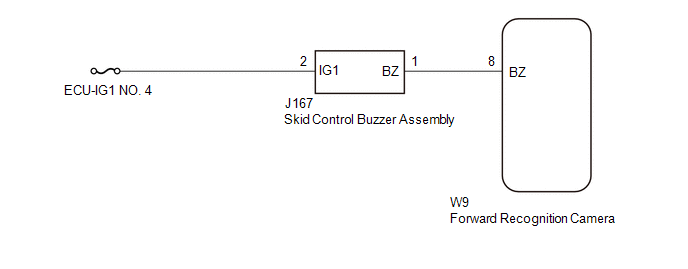
HINT: DTC will be output when conditions for either of the patterns in the table above are met. WIRING DIAGRAM
 CAUTION / NOTICE / HINT
NOTICE:
- Inspect the fuses for circuits related to this system before performing the following procedure.
- When replacing the forward recognition camera, always replace it with a
new one. If a forward recognition camera which was installed to another
vehicle is used, the information stored in the forward recognition
camera will not match the information from the vehicle. As a result, a
DTC may be stored.
- If the forward recognition camera has been replaced with a new one, be
sure to perform Forward Recognition Camera Axis Adjustment.
Click here 
PROCEDURE |
1. | CHECK FOR DTCs (FORWARD RECOGNITION CAMERA SYSTEM) |
(a) Clear the DTCs. Click here
(b) Perform the Active Test according to the display on the Techstream.
Click here NOTICE: Perform the Active Test for 1 second or more.
HINT: Performing the Active Test for 1 second or more causes DTC C1AA7 to be stored if the DTC detection conditions are met. |
Tester Display | Measurement Item |
Control Range | Diagnostic Note | |
PCS Buzzer | Skid control buzzer assembly |
ON / OFF | Test possible with ignition switch ON, vehicle stopped |
(c) Check for DTCs. Click here
|
Result | Proceed to | |
DTC C1AA7 is not output |
A | | DTC C1AA7 is output |
B |
| A |
 | USE SIMULATION METHOD TO CHECK |
|
B |
 | |
| 2. |
CHECK TERMINAL VOLTAGE |
| (a) Disconnect the skid control buzzer assembly connector. |
 |
|
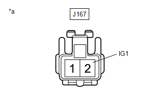
*a | Front view of wire harness connector
(to Skid Control Buzzer Assembly) | | |
(b) Measure the voltage according to the value(s) in the table below. Standard Voltage: |
Tester Connection | Switch Condition |
Specified Condition | |
J167-2 (IG1) - Body ground |
Ignition switch ON | 11 to 14 V | |
Ignition switch off | Below 1 V |
(c) Connect the skid control buzzer assembly connector.
| NG |
| REPAIR OR REPLACE HARNESS OR CONNECTOR (SKID CONTROL BUZZER ASSEMBLY - BATTERY) |
|
OK | |
| |
| 3. |
CHECK HARNESS AND CONNECTOR (SKID CONTROL BUZZER ASSEMBLY - FORWARD RECOGNITION CAMERA) |
(a) Disconnect the J167 skid control buzzer assembly connector. (b) Disconnect the W9 forward recognition camera connector.
(c) Measure the resistance according to the value(s) in the table below.
Standard Resistance: |
Tester Connection | Condition |
Specified Condition | |
J167-1 (BZ) - W9-8 (BZ) |
Always | Below 1 Ω | |
J167-1 (BZ) or W9-8 (BZ) - Body ground |
Always | 10 kΩ or higher |
(d) Connect the W9 forward recognition camera connector. (e) Connect the J167 skid control buzzer assembly connector.
| OK |
| GO TO STEP 6 |
|
NG | |
| |
| 4. |
REPAIR OR REPLACE HARNESS OR CONNECTOR (SKID CONTROL BUZZER ASSEMBLY - FORWARD RECOGNITION CAMERA) |
(a) Repair or replace the harness or connector.
|
NEXT | |
| |
| 5. |
CHECK FOR DTCs (FORWARD RECOGNITION CAMERA SYSTEM) |
(a) Clear the DTCs. Click here
(b) Perform the Active Test according to the display on the Techstream.
Click here NOTICE: Perform the Active Test for 1 second or more.
HINT: Performing the Active Test for 1 second or more causes DTC C1AA7 to be stored if the DTC detection conditions are met. |
Tester Display | Measurement Item |
Control Range | Diagnostic Note | |
PCS Buzzer | Skid control buzzer assembly |
ON / OFF | Test possible with ignition switch ON, vehicle stopped |
(c) Check for DTCs. Click here
|
Result | Proceed to | |
DTC C1AA7 is not output |
A | | DTC C1AA7 is output |
B |
| A |
| END |
|
B | |
| |
| 6. |
INSPECT SKID CONTROL BUZZER ASSEMBLY (CONFIRM BUZZER OPERATION) |
(a) Turn the ignition switch to ON. (b) Check if the skid control buzzer assembly is sounding.
|
Result | Proceed to | |
The skid control buzzer assembly does not sound when the ignition switch is turned to ON |
A | | The skid control buzzer assembly sounds continuously when the ignition switch is turned to ON |
B |
| B |
| GO TO STEP 8 |
|
A | |
| |
| 7. |
INSPECT SKID CONTROL BUZZER ASSEMBLY (UNIT INSPECTION) |
(a) Remove the skid control buzzer assembly. Click here
(b) Inspect the skid control buzzer assembly.
Click here
|
Result | Proceed to | |
Skid control buzzer assembly is abnormal |
A | | Skid control buzzer assembly is normal |
B |
| B |
| GO TO STEP 9 |
|
A | |
| |
| 8. |
REPLACE SKID CONTROL BUZZER ASSEMBLY | (a) Replace the skid control buzzer assembly.
Click here
|
NEXT | |
| |
| 9. |
CHECK FOR DTCs (FORWARD RECOGNITION CAMERA SYSTEM) |
(a) Clear the DTCs. Click here
(b) Perform the Active Test according to the display on the Techstream.
Click here NOTICE: Perform the Active Test for 1 second or more.
HINT: Performing the Active Test for 1 second or more causes DTC C1AA7 to be stored if the DTC detection conditions are met. |
Tester Display | Measurement Item |
Control Range | Diagnostic Note | |
PCS Buzzer | Skid control buzzer assembly |
ON / OFF | Test possible with ignition switch ON, vehicle stopped |
(c) Check for DTCs. Click here
|
Result | Proceed to | |
DTC C1AA7 is not output |
A | | DTC C1AA7 is output |
B |
| A |
| END |
| B |
| REPLACE FORWARD RECOGNITION CAMERA | | 

