ADJUSTMENT (SEQUENTIAL RECOGNITION) CAUTION / NOTICE / HINT NOTICE: Make sure to read Before Starting Adjustment before proceeding with work. Click here PROCEDURE 1. SECURE APPROPRIATE AREA FOR PERFORMING LEARNING
(b) Check the levelness of the ground. (1) Check the levelness of the ground at the 3 points shown in the illustration. 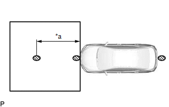
(2) Place the level on each levelness check point and check that the air bubble of the level is centered. 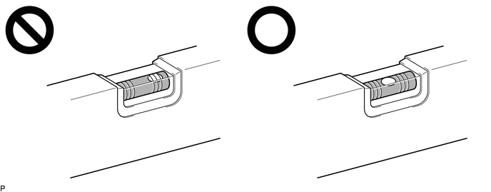 (c) Adjust the tire inflation pressure to the specified pressure. Click here (d) Clean the windshield glass. 2. CREATE TARGET NOTICE: Do not laminate the target or attach reflective materials, such as clear adhesive tape, to its surface. If there are reflective areas on the surface of the target, they will appear white to the forward recognition camera and the target may not be recognized. 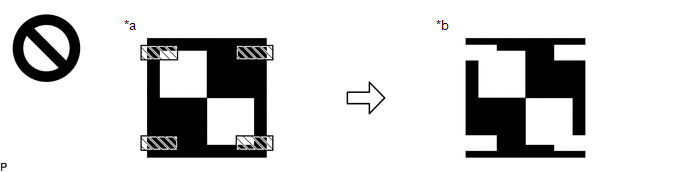
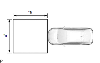
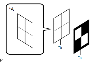
(a) Print the illustration.  (b) Check that the dimensions are within the values shown in the illustration. 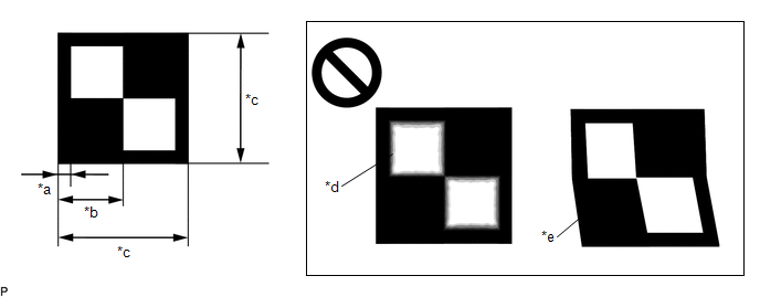
NOTICE:
HINT: If the dimensions of the created target sheet are not within +/- 5 mm (0.197 in.) of the specified values, adjust the printer settings and reprint the target sheet so that the dimensions are as specified. (c) Cut a piece of cardboard to be slightly larger than the target sheet. 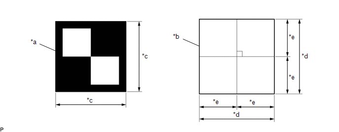
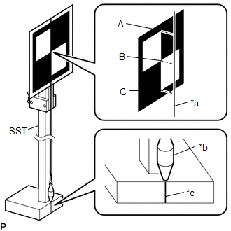
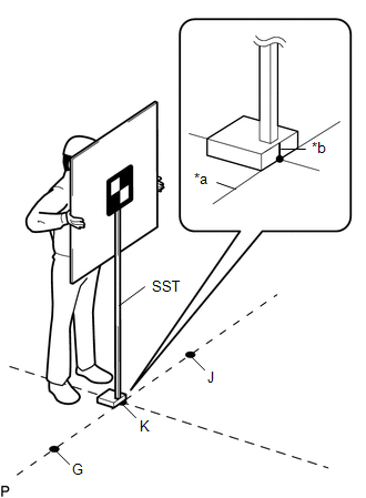
(e) Place the target sheet on the cardboard with the black area at the top right as shown in the illustration, and securely attach the target sheet using double-sided tape. NOTICE: Do not attach reflective materials, such as clear adhesive tape, to the target sheet surface as this may affect target recognition. (f) Remove SST (reflector) from SST (base stand). SST: 09870-60000 09870-60010 09870-60020 (g) Align the center of the target sheet with SST (reflector) and attach the target to SST (reflector) with double-sided tape. 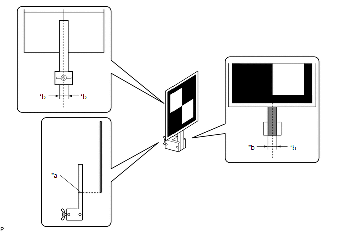
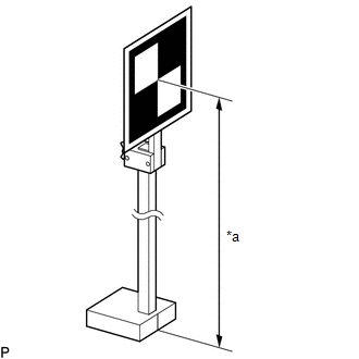
(h) Apply masking tape to the reflective surface of SST (reflector) to cover it. (i) Install SST (reflector) to SST (base stand).
(l) Prepare an object to block the area behind the target. (If there are any objects which may be misrecognized as a target behind the area where a target will be placed.) (1) When blocking the background by holding cardboard behind the target: 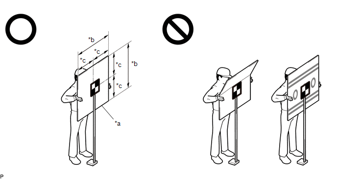
(2) When blocking the background using a light colored plain cloth: 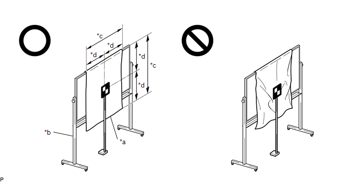
3. DETERMINE TARGET PLACEMENT POSITION (a) Determine the target placement position. 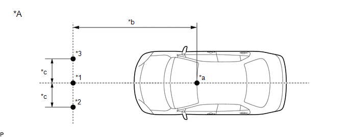
(b) Hang a weight with a pointed tip from the center of the tail gate handle assembly, and mark the rear center point of the vehicle (point A) on the ground. 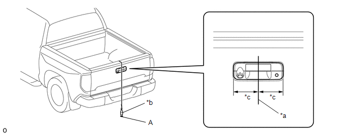
HINT: Lightly flick the string with your fingers several times to confirm that the string is perpendicular to the ground. (c) Hang a weight with a pointed tip from the center of the radiator grille emblem, and mark the front center point of the vehicle (point B) on the ground (placement position). (1) for Type A: 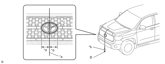
HINT: Lightly flick the string with your fingers several times to confirm that the string is perpendicular to the ground. (2) for Type B: 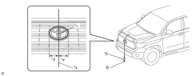
HINT: Lightly flick the string with your fingers several times to confirm that the string is perpendicular to the ground. (3) for Type C: 
HINT: Lightly flick the string with your fingers several times to confirm that the string is perpendicular to the ground. (d) Using tape and a string, create a line that connects point B to point A and extends at least 2200 mm (7.22 ft.) beyond the front center point of the vehicle. 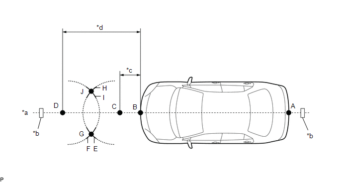
HINT:
(e) Mark point C at a position 525 mm (1.72 ft.) in front of point B. (f) Mark point D at a position 2195 mm (7.20 ft.) in front of point B. (g) Using a string, mark line E at a position 1000 mm (3.28 ft.) from point C. (h) Using a string, mark line H at a position 1000 mm (3.28 ft.) from point C. (i) Using a string, mark line F at a position 1000 mm (3.28 ft.) from point D. (j) Using a string, mark line I at a position 1000 mm (3.28 ft.) from point D. (k) Mark point G (placement point 2) at the point where line E and line F intersect. (l) Mark point J (placement point 3) at the point where line H and line I intersect. (m) Using tape and a string, create a line that connects point G and point J (target position line). 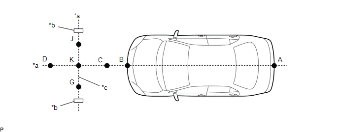
HINT:
(n) Mark point K (placement position 1) at the point the string connecting points C and D and the string connecting points G and J intersect. (o) Confirm that the distance between points K and G (placement positions 1 and 2), and K and J (placement positions 1 and 3) is 550 mm (21.65 in.). 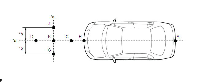
NOTICE: If the distance between either pair of points is not within +/- 3 mm (0.118 in.) of the specified value, start over from the marking of point A. 4. PERFORM FORWARD RECOGNITION CAMERA OPTICAL AXIS LEARNING NOTICE:
(a) Perform Recognition Camera/Target Position Memory. (1) Connect the Techstream to the DLC3. (2) Turn the ignition wsitch on (IG). (3) Turn the Techstream on. (4) Enter the following menus: Chassis / Front Recognition Camera / Utility / Recognition Camera/Target Position Memory. (5) Press "Next".*1 (6) Confirm the conditions displayed on the screen and then press "Next". (7) According to the display on the Techstream, enter the following values for each respective item.
(8) If "Recognition Camera/Target Position Memory has failed." is displayed on the Techstream screen, confirm the conditions displayed on the screen, then press "Yes" and repeat the procedure from *1. (9) Press "Exit" to exit the Recognition Camera/Target Position Memory utility. (b) Perform Recognition Camera Axis Adjust (target positioning).
(2) Enter the following menus: Chassis / Front Recognition Camera / Utility / Recognition Camera Axis Adjust. (3) Press "Next".*2 (4) Check that the values stored in the ECU are correct and then press "Next". (5) If "Failed to read axis adjustment data" is displayed, perform Recognition Camera/Target Position Memory, and repeat the procedure from *1. (6) Confirm the conditions displayed on the screen and then press "Next". (7) Check that the target is placed at point K (placement position 1) and then press "Next". HINT: If there are any objects which may be misrecognized as a target behind the area where a target will be placed, block the area behind the target with an appropriate object before pressing "Next". (8) Position SST at point G (placement position 2) and then point J (placement position 3) in the same manner as it was positioned at point K (placement position 1). NOTICE: Position SST and press "Next" within 3 minutes of the screen changing to the Recognition Camera Axis Adjust screen. (9) If "Recognition Camera Axis Adjust has failed." is displayed on the screen.
(10) If "Set the headlight type in the next screen." is displayed:
(11) If "Set the headlight type in the next screen." is not displayed:
(12) Turn the ignition wsitch off. (13) Disconnect the Techstream from the DLC3. (c) Forward recognition camera optical axis learning is complete. |
Toyota Tundra Service Manual > Sfi System: Drive Start Control
DESCRIPTION The drive start control is controlled by the ECM. If the ECM determines that the shift lever and accelerator pedal are operated abnormally, engine output is restricted and, when necessary, a warning is displayed on the combination meter assembly. CAUTION / NOTICE / HINT HINT: Even if the ...