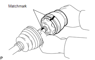
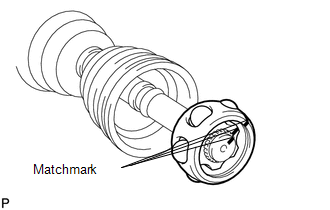
DISASSEMBLY PROCEDURE 1. REMOVE INBOARD JOINT BOOT CLAMP (a) Using a side cutter, cut the 2 inboard joint boot clamps and remove them. 2. DISCONNECT INBOARD JOINT BOOT (a) Disconnect the inboard joint boot from the inboard joint shaft. 3. REMOVE INBOARD JOINT SHAFT
(b) Using a screwdriver, remove the snap ring from the outboard joint shaft. (c) Remove the inboard joint shaft from the outboard joint shaft.
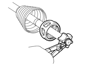
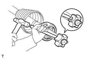
(e) Remove the 6 balls. (f) Slide the cage to the outboard joint side.
(i) Remove the cage. 4. REMOVE INBOARD JOINT BOOT (a) Remove the inboard joint boot from the outboard joint shaft. 5. REMOVE OUTBOARD JOINT BOOT CLAMP (a) Using a side cutter, cut the 2 outboard joint boot clamps and remove them. 6. REMOVE OUTBOARD JOINT BOOT (a) Remove the outboard joint boot from the outboard joint shaft. 7. REMOVE FRONT DRIVE SHAFT DUST COVER LH
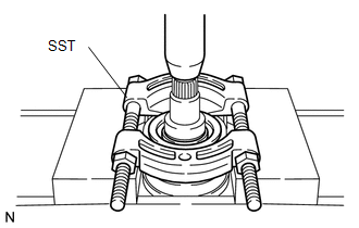
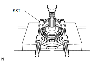
8. REMOVE DUST SEAL
|
Toyota Tundra Service Manual > Navigation System: Portable Player cannot be Registered
CAUTION / NOTICE / HINT HINT: Some versions of "Bluetooth" compatible audio players may not function, or the function may be limited using the navigation receiver assembly, even if the portable audio player itself can play files (See page ). PROCEDURE 1. CHECK THAT PORTABLE PLAYER IS "Bluetooth" AUD ...