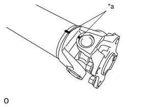
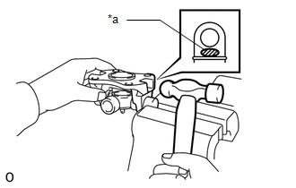
DISASSEMBLY PROCEDURE 1. REMOVE FRONT PROPELLER SHAFT JOINT SPIDER BEARING SNAP RING
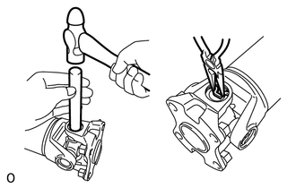
(c) Using needle-nose pliers, remove the 4 snap rings from the grooves. 2. REMOVE SPIDER BEARING 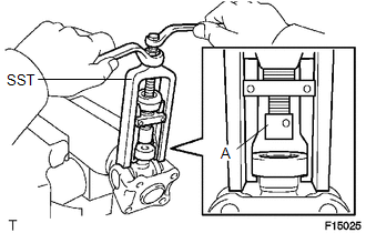 (a) Using SST, push out the bearing from the flange yoke. SST: 09332-25010 HINT: Before installing SST, sufficiently raise the part labeled A. If part A is too low, SST may be difficult to install.
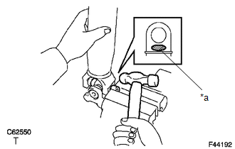
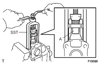
(d) Using SST, push the bearing out of the flange yoke. SST: 09332-25010 HINT: Before installing SST, sufficiently raise the part labeled A. If part A is too low, SST may be difficult to install.
(f) Remove the spider. Text in Illustration
HINT: Remove the bearing on the opposite side using the same procedure. |
Toyota Tundra Service Manual > Lighting System: Precaution
PRECAUTION PRECAUTION FOR BULB REPLACEMENT (a) Always prepare a new bulb for immediate replacement. While replacing a bulb, the lens may attract dust and moisture if removed from the vehicle for a long time. (b) Always replace a bulb with another bulb of the same wattage. (c) If only replacing the b ...