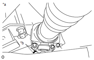
REMOVAL PROCEDURE 1. REMOVE PROPELLER SHAFT HEAT INSULATOR 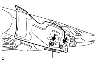 (a) Remove the 2 bolts and heat insulator from the heat insulator bracket. 2. REMOVE PROPELLER SHAFT HEAT INSULATOR BRACKET SUB-ASSEMBLY (a) Remove the 2 bolts and heat insulator bracket from the crossmember. 3. REMOVE FRONT PROPELLER SHAFT ASSEMBLY 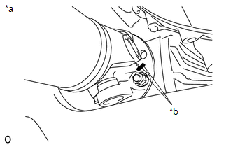 (a) for Front Differential Side: (1) Place matchmarks on the differential and propeller shaft flange. Text in Illustration
(2) Remove the 4 nuts, 4 washers and disconnect the propeller shaft from the differential. NOTICE: Use a rope to suspend the front edge of the propeller shaft.
(c) Remove the propeller shaft from the transfer flange. |
Toyota Tundra Service Manual > Audio And Visual System: Dtc Check / Clear
DTC CHECK / CLEAR 1. START DIAGNOSTIC MODE HINT: Illustrations may differ from the actual vehicle screen depending on the device settings and options. Therefore, some detailed areas may not be shown exactly the same as on the actual vehicle screen. If the system cannot enter the diagnostic mode, rep ...