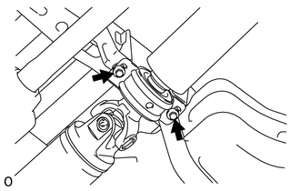
REMOVAL PROCEDURE 1. REMOVE PROPELLER WITH CENTER BEARING SHAFT ASSEMBLY  (a) Place matchmarks on the propeller shaft flange and differential flange. Text in Illustration
(b) Remove the 4 bolts and 4 nuts. Then disconnect the propeller shaft from the differential side.
(d) w/ Bearing Washer: Remove the 2 mounting bolts and 2 bearing washers from the crossmember. (e) Remove the propeller shaft.
|
Toyota Tundra Service Manual > Wiper / Washer: Washer Nozzle
Adjustment ADJUSTMENT PROCEDURE 1. ADJUST WASHER NOZZLE SUB-ASSEMBLY (a) Using a screwdriver, detach the 2 claws and separate the washer nozzle. NOTICE: Be careful not to damage the windshield. (b) Remove the washer nozzle from the washer hose. NOTICE: Washer nozzles cannot be reused. (c) Select a w ...