Components COMPONENTS ILLUSTRATION 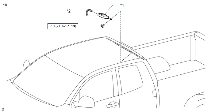
ILLUSTRATION 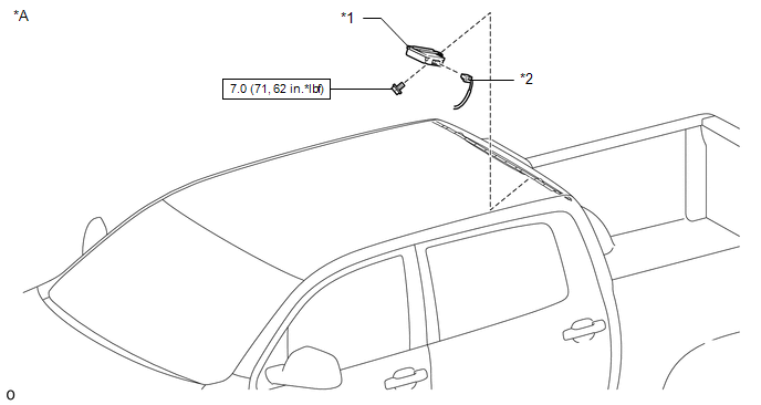
Installation INSTALLATION PROCEDURE 1. INSTALL TIRE PRESSURE WARNING ECU AND RECEIVER (a) Connect the connector to the tire pressure warning ECU and receiver. (b) Attach the 2 guides to temporarily install the tire pressure warning ECU and receiver. (c) Install the bolt. Torque: 7.0 N·m {71 kgf·cm, 62 in·lbf} 2. INSTALL ROOF HEADLINING ASSEMBLY
Removal REMOVAL PROCEDURE 1. REMOVE ROOF HEADLINING ASSEMBLY
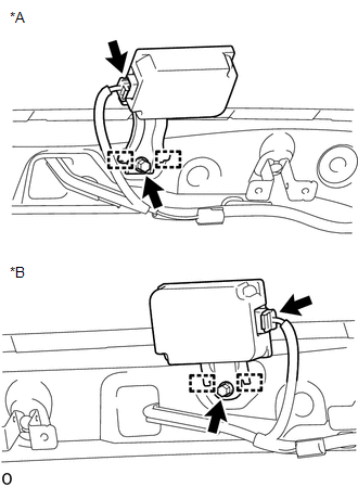
2. REMOVE TIRE PRESSURE WARNING ECU AND RECEIVER
(b) Detach the 2 guides to remove the tire pressure warning ECU and receiver. (c) Disconnect the connector from the tire pressure warning ECU and receiver. |
Toyota Tundra Service Manual > Navigation System: Problem Symptoms Table
PROBLEM SYMPTOMS TABLE NOTICE: After replacing the stereo component tuner assembly of vehicles subscribed to pay-type satellite radio broadcasts, XM radio ID registration is necessary (w/ SDARS System). HINT: Use the table below to help determine the cause of problem symptoms. If multiple suspected ...