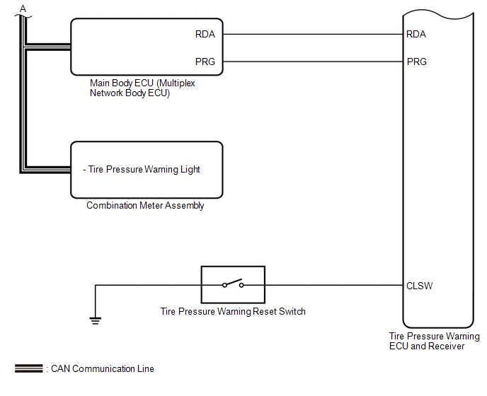
Toyota Tundra Service Manual: System Diagram

SYSTEM DIAGRAM

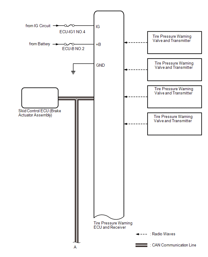
HINT:

Each tire pressure warning valve and transmitter sends its transmitter ID, temperature and tire pressure information to the tire pressure warning ECU and receiver.

Transmitting ECU (Transmitter)

Receiving ECU

Signal

Communication Method

Combination Meter Assembly

Main Body ECU (Multiplex Network Body ECU)

Vehicle speed signal

CAN communication line

Main Body ECU (Multiplex Network Body ECU)

Combination Meter Assembly

Tire pressure warning light signal

CAN communication line

Skid Control ECU (Brake Actuator Assembly)

Tire Pressure Warning ECU and Receiver

Speed sensor signal

CAN communication line

    Registration

    Terminals Of Ecu

    See More:

    Toyota Tundra Service Manual > Differential Carrier Assembly(for 1ur-fe): Reassembly
    REASSEMBLY PROCEDURE 1. INSTALL DIFFERENTIAL CASE ASSEMBLY (a) Install the 2 side gear thrust washers to the side gears. (b) Install the 2 side gears with the thrust washers, 2 pinion gears, 2 pinion gear thrust washers and pinion shaft. HINT: Align the holes for the straight pin in the differential ...

    Toyota Tundra Owners Manual

    Toyota Tundra Service Manual

    © 2025 Copyright www.ttundra.com
    0.0348