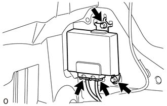
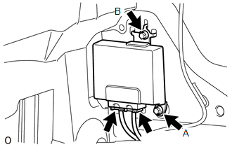
Components COMPONENTS ILLUSTRATION 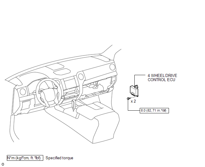 Installation INSTALLATION PROCEDURE 1. INSTALL 4 WHEEL DRIVE CONTROL ECU (a) Connect the 2 connectors.
2. INSTALL CLEARANCE WARNING ECU WITH BRACKET (See page
3. INSTALL LOWER INSTRUMENT PANEL FINISH PANEL SUB-ASSEMBLY RH
4. CONNECT CABLE TO NEGATIVE BATTERY TERMINAL NOTICE: When disconnecting the cable, some systems need to be initialized after the cable is reconnected (See page
Removal REMOVAL PROCEDURE 1. PRECAUTION NOTICE: After
turning the ignition switch off, waiting time may be required before
disconnecting the cable from the negative (-) battery terminal.
Therefore, make sure to read the disconnecting the cable from the
negative (-) battery terminal notice before proceeding with work (See
page 2. DISCONNECT CABLE FROM NEGATIVE BATTERY TERMINAL NOTICE: When disconnecting the cable, some systems need to be initialized after the cable is reconnected (See page
3. REMOVE LOWER INSTRUMENT PANEL FINISH PANEL SUB-ASSEMBLY RH
4. REMOVE CLEARANCE WARNING ECU WITH BRACKET (See page
5. REMOVE 4 WHEEL DRIVE CONTROL ECU
(b) Remove the 2 bolts and 4 wheel drive control ECU. NOTICE:
|
Toyota Tundra Service Manual > Air Conditioning System(for Automatic Air Conditioning System): Actuator Check
ACTUATOR CHECK 1. ACTUATOR CHECK (a) Turn the ignition switch ON while pressing the A/C control AUTO switch and Recirculation / Fresh switch simultaneously. (b) Press the Recirculation / Fresh switch. (c) As each damper, motor and relay automatically operate the actuator check at 1 second intervals ...

 )
)