Toyota Tundra Service Manual: Transfer Synchronization Actuator Circuit High (P17A7)

Toyota Tundra Service Manual / Engine, Hybrid System / Wf1am Transfer / Touch Select 2-4 And High-low System / Transfer Synchronization Actuator Circuit High (P17A7)

DESCRIPTION

This DTC is detected when a short to B+ is detected in the solenoid coil drive circuit.

DTC Code

DTC Detection Condition

  1. Diagnosis Condition
  2. Malfunction Status
  3. Malfunction Time
  4. Other

Trouble Area

P17A7

  1. Ignition switch ON (when not switching between 2WD and 4H)
  2. Short to B+ in the solenoid coil drive circuit
  3. 1 second or more
  4. 1 trip detection logic
  • Wire harness and connector
  • 4 wheel drive control ECU
  • Solenoid coil sub-assembly
  • Transfer shift actuator assembly

WIRING DIAGRAM

Refer to DTCs P17A5 and P17A6 (See page ).

PROCEDURE

1.

CHECK SOLENOID COIL SUB-ASSEMBLY

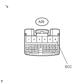
(a) Disconnect the 4 wheel drive control ECU connector.

(b) Measure the voltage according to the value(s) in the table below.

Standard Voltage:

Tester Connection

Switch Condition

Specified Condition

A26-6 (SCC) - Body ground

Ignition switch ON

Below 1 V

Text in Illustration

*a

Front view of wire harness connector

(to 4 Wheel Drive Control ECU)

OK

REPLACE 4 WHEEL DRIVE CONTROL ECU

NG

2.

CHECK HARNESS AND CONNECTOR (4 WHEEL DRIVE CONTROL ECU AND TRANSFER SHIFT ACTUATOR ASSEMBLY - BODY GROUND)

(a) Disconnect the A26 4 wheel drive control ECU connector.

(b) Disconnect the D67 transfer shift actuator assembly connector.

(c) Measure the voltage according to the value(s) in the table below.

Standard Voltage:

Tester Connection

Switch Condition

Specified Condition

A26-6 (SCC) or D67-3 (SCC) - Body ground

Ignition switch ON

Below 1 V

NG

REPAIR OR REPLACE HARNESS OR CONNECTOR

OK

3.

INSPECT SOLENOID COIL SUB-ASSEMBLY

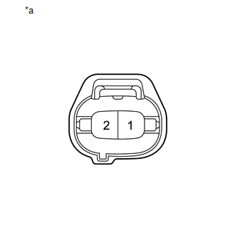
(a) Disconnect the A solenoid coil sub-assembly connector.

(b) Measure the voltage according to the value(s) in the table below.

Standard Voltage:

Tester Connection

Switch Condition

Specified Condition

2 - Body ground

Ignition switch ON

Below 1 V

Text in Illustration

*a

Component without harness connected

(Solenoid Coil Sub-assembly)

OK

REPLACE TRANSFER SHIFT ACTUATOR ASSEMBLY

NG

REPLACE SOLENOID COIL SUB-ASSEMBLY

    Transfer Synchronization Actuator Circuit Open (P17A5,P17A6)

    Transfer Shift Motor Control Circuit Circuit Open (P17A8,P17A9)

    See More:

    Toyota Tundra Service Manual > Power Mirror Control System(w/ Memory): System Diagram
    SYSTEM DIAGRAM 1. POWER MIRROR CONTROL SYSTEM Communication Table Sender Receiver Communication Signal Communication Line Main body ECU (multiplex network body ECU) Outer mirror control ECU assembly Mirror master switch signal Mirror control switch signal Mirror retract switch signal CAN ECM Outer m ...

    Toyota Tundra Owners Manual

    Toyota Tundra Service Manual

    © 2024 Copyright www.ttundra.com
    0.0335