DESCRIPTION This DTC is detected when a short to B+ is detected in the transfer shift motor drive circuit.
WIRING DIAGRAM Refer to DTCs P17A8 and P17A9 (See page PROCEDURE
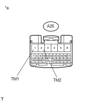 (a) Disconnect the 4 wheel drive control ECU connector. (b) Measure the voltage according to the value(s) in the table below. Standard Voltage:
(a) Disconnect the A26 4 wheel drive control ECU connector. (b) Disconnect the D67 transfer shift actuator assembly connector. (c) Measure the voltage according to the value(s) in the table below. Standard Voltage:
|
Toyota Tundra Service Manual > Rear Seat Assembly(for Crewmax Lh Side): Reassembly
REASSEMBLY CAUTION / NOTICE / HINT CAUTION: Wear protective gloves. Sharp areas on the parts may injure your hands. PROCEDURE 1. INSTALL REAR SEATBACK FRAME SUB-ASSEMBLY LH (a) Install the rear seatback frame sub-assembly LH with the 5 bolts. Torque: for Bolt A : 85 N·m {867 kgf·cm, 63 ft·lbf} fo ...

 ).
).


