DESCRIPTION This DTC is
detected when a malfunction is detected in the limit switch circuit,
which detects the position of the transfer shift motor. |
DTC Code | DTC Detection Condition
- Diagnosis Condition
- Malfunction Status
- Malfunction Time
- Other
| Trouble Area | |
P17AC |
- When the ignition switch is ON, the engine is running, and the driving mode is being switched
- The combination of the TL1, TL2, TL3 and TL4 terminal signals is
abnormal or the TL1, TL2, TL3 and TL4 terminal signal switching order is
abnormal
- 0.02 seconds or more
- 1 trip detection logic
|
- Wire harness and connector
- 4 wheel drive control ECU
- Transfer shift actuator assembly
| WIRING DIAGRAM
Refer to DTC P17AB (See page  ). ). PROCEDURE
| 1. |
CHECK HARNESS AND CONNECTOR (4 WHEEL DRIVE CONTROL ECU - TRANSFER SHIFT ACTUATOR ASSEMBLY) |
(a) Disconnect the A26 4 wheel drive control ECU connector. (b) Disconnect the D68 transfer shift actuator assembly connector.
(c) Measure the resistance according to the value(s) in the table below.
Standard Resistance: |
Tester Connection | Condition |
Specified Condition | |
A26-18 (TL1) - D68-1 (TL1) |
Always | Below 1 Ω | |
A26-20 (TL2) - D68-2 (TL2) |
Always | Below 1 Ω | |
A26-26 (TL3) - D68-3 (TL3) |
Always | Below 1 Ω | |
A26-24 (TL4) - D68-4 (TL4) |
Always | Below 1 Ω | |
A26-22 (GTL) - D68-5 (GTL) |
Always | Below 1 Ω | |
A26-18 (TL1) or D68-1 (TL1) - Body ground |
Always | 10 kΩ or higher | |
A26-20 (TL2) or D68-2 (TL2) - Body ground |
Always | 10 kΩ or higher | |
A26-26 (TL3) or D68-3 (TL3) - Body ground |
Always | 10 kΩ or higher | |
A26-24 (TL4) or D68-4 (TL4) - Body ground |
Always | 10 kΩ or higher | |
A26-18 (TL1) - D68-2 (TL2), D68-3 (TL3), D68-4 (TL4) and D68-5 (GTL) |
Always | 10 kΩ or higher | |
A26-20 (TL2) - D68-1 (TL1), D68-3 (TL3), D68-4 (TL4) and D68-5 (GTL) |
Always | 10 kΩ or higher | |
A26-26 (TL3) - D68-1 (TL1), D68-2 (TL2), D68-4 (TL4) and D68-5 (GTL) |
Always | 10 kΩ or higher | |
A26-24 (TL4) - D68-1 (TL1), D68-2 (TL2), D68-3 (TL3) and D68-5 (GTL) |
Always | 10 kΩ or higher |
| NG |
 | REPAIR OR REPLACE HARNESS OR CONNECTOR |
|
OK |
 | |
| 2. |
CHECK 4 WHEEL DRIVE CONTROL ECU (ECU OUTPUT VOLTAGE) |
 (a) Disconnect the transfer shift actuator assembly connector.
(b) Measure the voltage according to the value(s) in the table below. Standard Voltage: |
Tester Connection | Switch Condition |
Specified Condition | |
D68-1 (TL1) - Body ground |
Ignition switch ON | 4 to 6 V | |
D68-2 (TL2) - Body ground |
Ignition switch ON | 4 to 6 V | |
D68-3 (TL3) - Body ground |
Ignition switch ON | 4 to 6 V | |
D68-4 (TL4) - Body ground |
Ignition switch ON | 4 to 6 V | Text in Illustration |
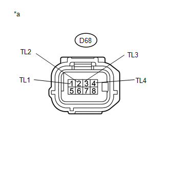
*a | Front view of wire harness connector
(to Transfer Shift Actuator Assembly) |
| OK |
| REPLACE TRANSFER SHIFT ACTUATOR ASSEMBLY |
| NG |
| REPLACE 4 WHEEL DRIVE CONTROL ECU | |


