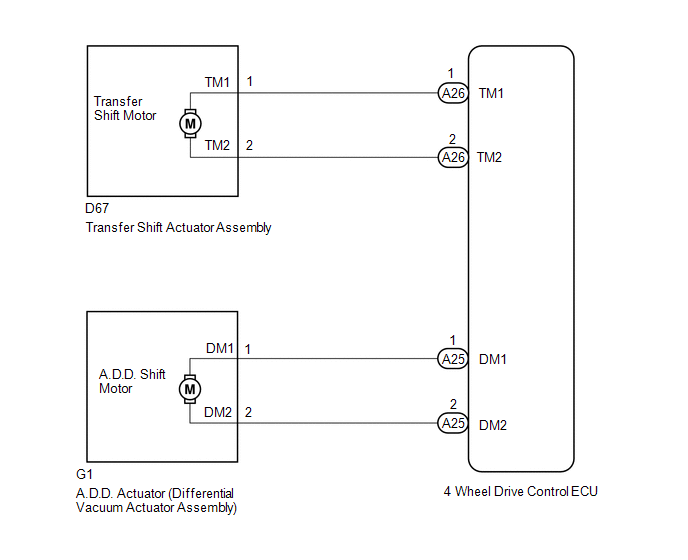
WIRING DIAGRAM
 CAUTION / NOTICE / HINT
NOTICE: When
the vehicle is stopped, mode switching may be unavailable due to the
phase of the transfer assembly and A.D.D. actuator powertrain. There is
no malfunction if mode switching is available after the vehicle is
moved. PROCEDURE |
1. | CONFIRM PROBLEM SYMPTOM |
(a) Confirm the problem symptoms. Result |
Result | Proceed to | |
The 4HI indicator light is blinking* |
A | | The 4LO indicator light is blinking* |
B |
- *: Blinks at 0.5 second intervals (0.5 seconds on and 0.5 seconds off)
| B |
 | GO TO STEP 3 |
|
A |
 | |
(a) Move the shift lever to N.
(b) Turn the transfer position switch from 2WD to 4H. HINT: The 4HI indicator light continues to blink.
(c) Lift up the vehicle until the 2 front wheels or all four wheels are off the ground.
(d) Release the parking brake. (e) Rotate the rear propeller shaft and check that the front propeller shaft rotates. Result |
Result | Proceed to | |
The front propeller shaft rotates |
A | | The front propeller shaft does not rotate |
B |
| A |
| REPLACE DIFFERENTIAL VACUUM ACTUATOR ASSEMBLY |
|
B | |
| |
| 3. |
CHECK TRANSFER SHIFT ACTUATOR ASSEMBLY (TRANSFER SHIFT MOTOR) |
 (a) Disconnect the 4 wheel drive control ECU connector.
(b) Measure the resistance according to the value(s) in the table below.
Standard Resistance: |
Tester Connection | Condition |
Specified Condition | |
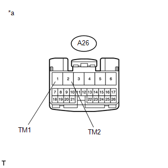
A26-1 (TM1) - A26-2 (TM2) |
Always | 1 Ω or higher | Text in Illustration |
*a | Front view of wire harness connector
(to 4 Wheel Drive Control ECU) | Result |
Result | Proceed to | |
OK | A | |
NG (when 4HI indicator light is blinking*) |
B | | NG (when 4LO indicator light is blinking*) |
C |
| B |
| GO TO STEP 5 |
| C |
| REPLACE 4 WHEEL DRIVE CONTROL ECU |
|
A | |
| |
| 4. |
CHECK HARNESS AND CONNECTOR (4 WHEEL DRIVE CONTROL ECU - TRANSFER SHIFT ACTUATOR ASSEMBLY) |
(a) Disconnect the A26 4 wheel drive control ECU connector. (b) Disconnect the D67 transfer shift actuator assembly connector.
(c) Measure the resistance according to the value(s) in the table below.
Standard Resistance: |
Tester Connection | Condition |
Specified Condition | |
A26-1 (TM1) or D67-1 (TM1) - A26-2 (TM2) or D67-2 (TM2) |
Always | 10 kΩ or higher |
| OK |
| REPLACE TRANSFER SHIFT ACTUATOR ASSEMBLY |
| NG |
| REPAIR OR REPLACE HARNESS OR CONNECTOR |
| 5. |
CHECK DIFFERENTIAL VACUUM ACTUATOR ASSEMBLY (A.D.D. SHIFT MOTOR) |
 (a) Disconnect the 4 wheel drive control ECU connector.
(b) Measure the resistance according to the value(s) in the table below.
Standard Resistance: |
Tester Connection | Condition |
Specified Condition | |
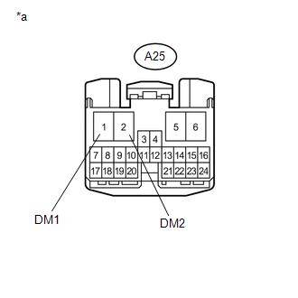
A25-1 (DM1) - A25-2 (DM2) |
Always | 0.5 Ω or higher | Text in Illustration |
*a | Front view of wire harness connector
(to 4 Wheel Drive Control ECU) |
| NG |
| REPLACE 4 WHEEL DRIVE CONTROL ECU |
|
OK | |
| |
| 6. |
CHECK HARNESS AND CONNECTOR ( 4 WHEEL DRIVE CONTROL ECU -DIFFERENTIAL VACUUM ACTUATOR ASSEMBLY) |
(a) Disconnect the A25 4 wheel drive control ECU connector. (b) Disconnect the G1 A.D.D. actuator (differential vacuum actuator assembly) connector.
(c) Measure the resistance according to the value(s) in the table below.
Standard Resistance: |
Tester Connection | Condition |
Specified Condition | |
A25-1 (DM1) or G1-1 (DM1) - A25-2 (DM2) or G1-2 (DM2) |
Always | 10 kΩ or higher |
| OK |
| REPLACE DIFFERENTIAL VACUUM ACTUATOR ASSEMBLY |
| NG |
| REPAIR OR REPLACE HARNESS OR CONNECTOR | | 

