DISASSEMBLY PROCEDURE 1. REMOVE LOWER TRANSFER CASE PROTECTOR
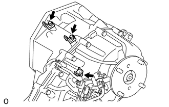
(a) Remove the 4 bolts and lower transfer case protector. 2. REMOVE WIRING HARNESS CLAMP BRACKET
| (a) Remove the 3 bolts and 3 wiring harness clamp brackets. |
|
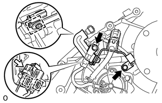
| (b) Disconnect the connector and 3 clamps. | |
(c) Remove the 2 bolts and wiring harness clamp bracket. 3. REMOVE TRANSFER SHIFT ACTUATOR ASSEMBLY
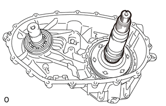
 4. REMOVE OUTPUT SHAFT COMPANION FLANGE SUB-ASSEMBLY (REAR)
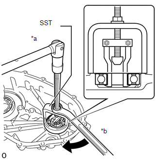
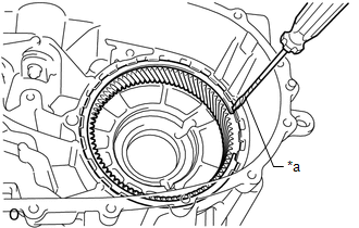
| (a) Using a chisel and hammer, loosen the staked part of the transfer output shaft nut.
NOTICE:
- Completely loosen the staked part of the transfer output shaft nut when removing it.
- Do not damage the threads of the rear transfer output shaft.
| |
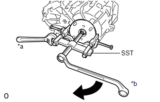
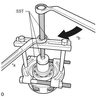
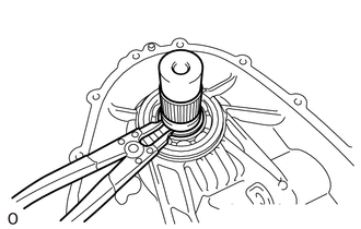
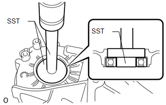
(b) Using SST, hold the output shaft companion flange sub-assembly (rear).
SST: 09330-00021 Text in Illustration
(c) Using a 30 mm socket wrench, remove the transfer output shaft nut.
(d) Remove the O-ring. |
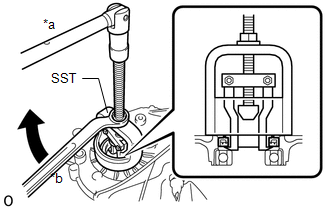
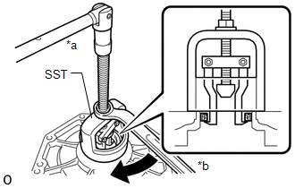
(e) Using SST, remove the output shaft companion flange sub-assembly (rear).
SST: 09950-40011 09951-04020 09952-04010 09953-04030
09954-04010 09955-04031 09957-04010 09958-04011 Text in Illustration |
|
5. REMOVE TRANSFER OUTPUT SHAFT TYPE T OIL SEAL
6. REMOVE TRANSFER INDICATOR SWITCH
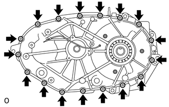
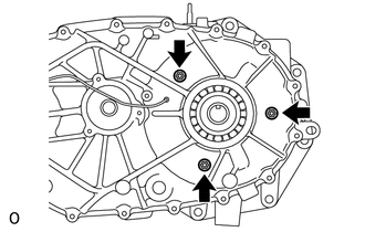
7. REMOVE REAR TRANSFER CASE
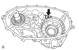
| (a) Using a 40 IP ''TORX PLUS'' socket wrench or T40 ''TORX'' socket wrench, remove the 17 bolts. |
|
(b) Remove the rear transfer case. HINT: If necessary, tap the rear transfer case with a plastic-faced hammer to remove it.
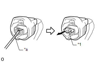
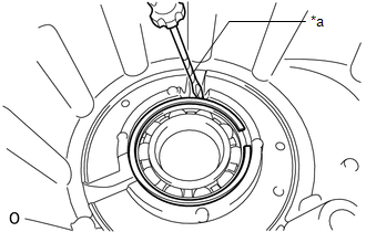
8. REMOVE SOLENOID COIL SUB-ASSEMBLY (a) Disconnect the solenoid coil sub-assembly terminal.
| (1) Remove the retainer from the coupler as shown in the illustration. Text in Illustration |
*1 | Retainer | |
*a | Protective Tape | |
|
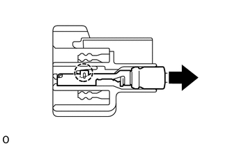
| (2) Detach the claw and disconnect the solenoid coil sub-assembly terminal. |
|
| (b) Remove the 3 nuts and solenoid coil sub-assembly. NOTICE:
Be careful not to drop the solenoid coil sub-assembly. | |
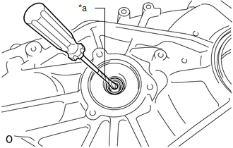
9. REMOVE TRANSFER COVER TYPE T OIL SEAL
| (a) Using a screwdriver, remove the transfer cover type T oil seal. Text in Illustration
NOTICE: Do not damage the rear transfer case. HINT: Tape the screwdriver tip before use. |
|
10. REMOVE TRANSFER DRIVEN SPROCKET BEARING (REAR)
| (a) Using SST, remove the transfer driven sprocket bearing (rear).
SST: 09612-65014 09612-01040 Text in Illustration |
|
11. REMOVE REAR TRANSFER OUTPUT SHAFT RADIAL BALL BEARING
| (a) Using a screwdriver, remove the transfer output shaft rear shaft snap ring. Text in Illustration
HINT: Tape the screwdriver tip before use. | |
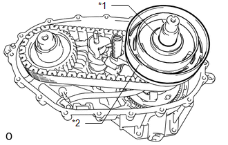
(b) Remove the rear transfer output shaft radial ball bearing. 12. REMOVE SOLENOID COVER
| (a) Remove the No. 1 transfer output shaft spacer and solenoid cover. Text in Illustration |
*1 | No. 1 Transfer Output Shaft Spacer | |
*2 | Solenoid Cover | |
|
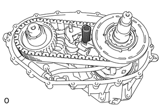
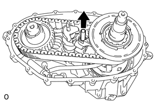
13. REMOVE TRANSFER SELECT RETURN SPRING
| (a) Remove the transfer select return spring. | |
14. REMOVE TRANSFER HIGH AND LOW SHIFT FORK SHAFT
| (a) Remove the transfer high and low shift fork shaft. |
|
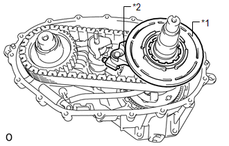
15. REMOVE SOLENOID LOCK PLATE WITH NO. 2 TRANSFER GEAR SHIFT FORK
| (a) Remove the solenoid lock plate together with the No. 2 transfer gear shift fork. Text in Illustration |
*1 | Solenoid Lock Plate | |
*2 | No. 2 Transfer Gear Shift Fork | |
|
(b) Remove the No. 2 transfer gear shift fork from the solenoid lock plate.
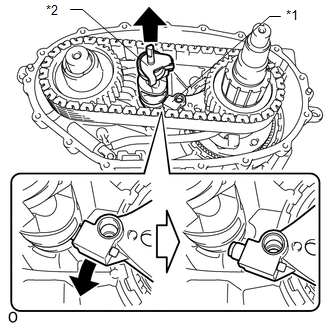
16. REMOVE CONTROL SELECT SHAFT SUB-ASSEMBLY
| (a)
Remove the No. 1 transfer gear shift fork from the side of the control
select shaft sub-assembly as shown in the illustration. Then remove the
control select shaft sub-assembly. Text in Illustration |
*1 | No. 1 Transfer Gear Shift Fork | |
*2 | Control Select Shaft Sub-assembly | |
|
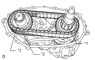
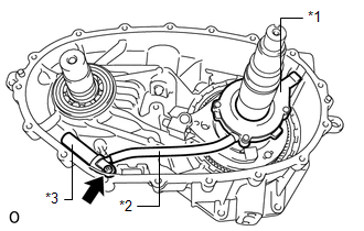
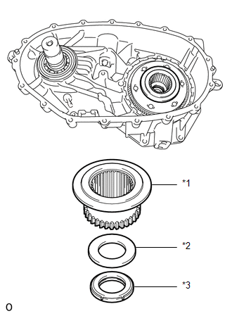
17. REMOVE TRANSFER DRIVE SPROCKET SUB-ASSEMBLY
| (a) Remove the transfer drive sprocket sub-assembly together with the front transfer drive chain and transfer driven sprocket. Text in Illustration |
*1 | Transfer Drive Sprocket Sub-assembly | |
*2 | Front Transfer Drive Chain | |
*3 | Transfer Driven Sprocket |
NOTICE: Do not drop the transfer drive sprocket sub-assembly, front transfer drive chain and transfer driven sprocket. |
|
(b) Remove the transfer drive sprocket sub-assembly and transfer driven sprocket from the front transfer drive chain.
18. REMOVE TRANSFER OIL PUMP BODY SUB-ASSEMBLY
| (a)
Using a T25 ''TORX'' socket wrench, remove the bolt and the transfer
oil pump body sub-assembly together with the transfer oil tube and
transfer oil strainer sub-assembly. Text in Illustration |
*1 | Transfer Oil Pump Body Sub-assembly | |
*2 | Transfer Oil Tube | |
*3 | Transfer Oil Strainer Sub-assembly |
HINT: The sleeve does not have to be removed. The transfer oil strainer sub-assembly comes with the sleeve installed. |
|
(b) Remove the transfer oil tube from the transfer oil pump body sub-assembly.
(c) Remove the transfer oil strainer sub-assembly from the transfer oil tube.
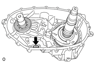
19. REMOVE TRANSFER CASE MAGNET
| (a) Remove the transfer case magnet. | |
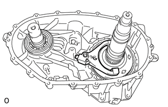
20. REMOVE NO. 1 TRANSFER GEAR SHIFT FORK
| (a) Remove the No. 1 transfer gear shift fork. | |
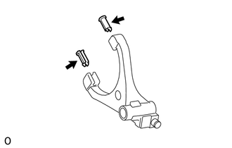
(b) Inspect the gear shift fork pad (See page ).
| (c) Remove the 2 gear shift fork pads from the No. 1 transfer gear shift fork.
HINT: It is not necessary to remove the 2 gear shift fork pads unless they are being replaced. |
|
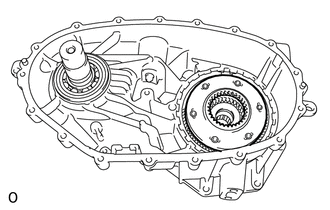
21. REMOVE REAR TRANSFER OUTPUT SHAFT
| (a) Remove the rear transfer output shaft. | |
22. REMOVE TRANSFER HIGH AND LOW CLUTCH SLEEVE
| (a)
Remove the transfer high and low clutch sleeve, No. 2 transfer output
shaft spacer and transfer lower planetary gear bearing. Text in Illustration |
*1 | Transfer High and Low Clutch Sleeve | |
*2 | No. 2 Transfer Output Shaft Spacer | |
*3 | Transfer Lower Planetary Gear Bearing | |
|
23. REMOVE TRANSFER LOWER PLANETARY GEAR ASSEMBLY
| (a) Remove the transfer lower planetary gear assembly. |
|
| (b) Using SST, remove the transfer input gear radial ball bearing.
SST: 09950-00020 SST: 09950-00030 SST: 09950-60010 09951-00480 Text in Illustration |
|
24. REMOVE TRANSFER LOWER PLANETARY RING GEAR
| (a) Using a screwdriver, remove the transfer lower planetary ring gear hole snap ring. Text in Illustration
HINT: Tape the screwdriver tip before use. | |
(b) Remove the transfer lower planetary ring gear. 25. REMOVE TRANSFER OIL SEPARATOR
| (a) Using a T25 ''TORX'' socket wrench, remove the bolt and transfer oil separator. |
|
26. REMOVE OUTPUT SHAFT COMPANION FLANGE SUB-ASSEMBLY (FRONT)
| (a) Using a snap ring expander, remove the shaft snap ring and output shaft companion flange sub-assembly (front).
NOTICE: Do not drop the output shaft companion flange sub-assembly (front). |
|
27. REMOVE NO. 2 TRANSFER CASE OIL SEAL
| (a) Using SST, remove the No. 2 transfer case oil seal. SST: 09612-65014
09612-01020 Text in Illustration |
|
28. REMOVE TRANSFER DRIVEN SPROCKET BEARING (FRONT)
| (a) Using SST and a press, press out the transfer driven sprocket bearing (front).
SST: 09950-60010 09951-00390 09952-06010 SST: 09950-60020
09951-00730 SST: 09950-70010 09951-07100 | |
29. REMOVE TRANSFER CASE OIL SEAL
| (a) Using SST, remove the transfer case oil seal. SST: 09612-65014
09612-01020 Text in Illustration |
| |