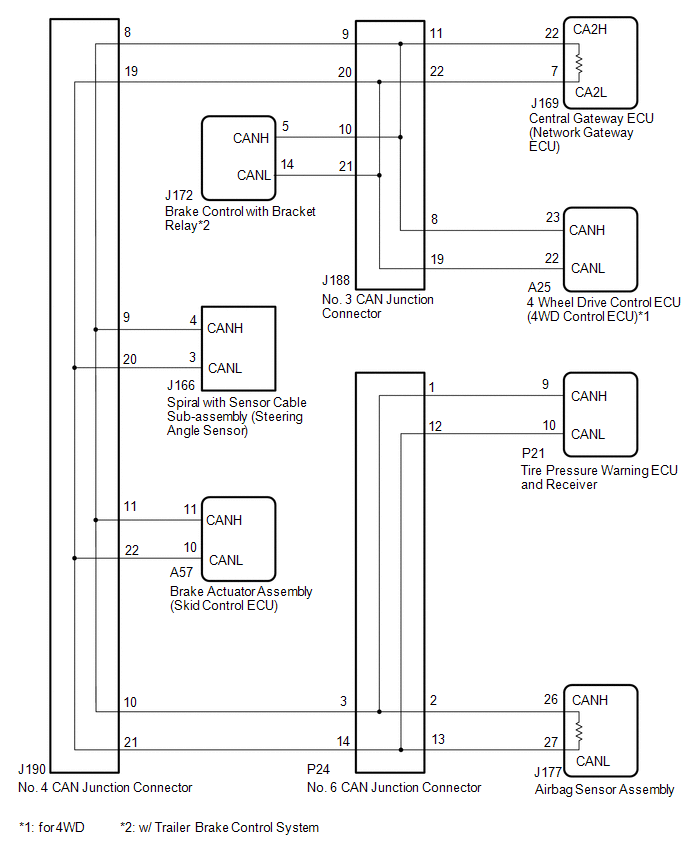
DESCRIPTION There may be a
short circuit between the CAN main bus lines and/or CAN branch lines
when the resistance between terminals 22 (CA2H) and 7 (CA2L) of the
central gateway ECU (network gateway ECU) is below 54 Ω. |
Symptom | Trouble Area |
|
*1: for 4WD
*2: w/ Trailer Brake Control System | |
Resistance between terminals 22 (CA2H) and 7 (CA2L) of the central gateway ECU (network gateway ECU) is below 54 Ω. |
- Short in CAN main bus lines
- Short in CAN branch lines
- Central gateway ECU (network gateway ECU)
- 4 wheel drive control ECU (4WD control ECU)*1
- Tire pressure warning ECU and receiver
- Airbag sensor assembly
- Brake control with bracket relay*2
- Spiral with sensor cable sub-assembly (steering angle sensor)
- Brake actuator assembly (skid control ECU)
- No. 3 CAN junction connector
- No. 4 CAN junction connector
- No. 6 CAN junction connector
| WIRING DIAGRAM
 CAUTION / NOTICE / HINT
CAUTION: When performing the confirmation driving pattern, obey all speed limits and traffic laws.
NOTICE:
HINT:
- Before disconnecting related connectors for inspection, push in on each
connector body to check that the connector is not loose or disconnected.
- When a connector is disconnected, check that the terminals and connector body are not cracked, deformed or corroded.
PROCEDURE |
1. | CHECK FOR SHORT IN CAN BUS WIRES (NO. 4 CAN JUNCTION CONNECTOR) |
(a) Disconnect the cable from the negative (-) battery terminal.
| (b) Disconnect the No. 4 CAN junction connector. |
 |
|
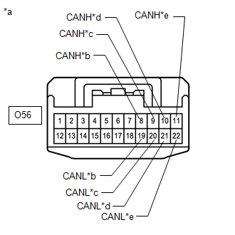
*a | Front view of wire harness connector
(to No. 4 CAN Junction Connector) | |
*b | to No. 3 CAN Junction Connector | |
*c | to Spiral with Sensor Cable Sub-assembly (Steering Angle Sensor) | |
*d | to No. 6 CAN Junction Connector | |
*e | to Brake Actuator Assembly (Skid Control ECU) | | |
(c) Measure the resistance according to the value(s) in the table below.
Standard Resistance: |
Tester Connection | Condition |
Specified Condition | Connected to | |
J190-8 (CANH) - J190-19 (CANL) |
Cable disconnected from negative (-) battery terminal |
108 to 132 Ω | No. 3 CAN junction connector | |
J190-9 (CANH) - J190-20 (CANL) |
Cable disconnected from negative (-) battery terminal |
200 Ω or higher | Spiral with sensor cable sub-assembly (steering angle sensor) | |
J190-10 (CANH) - J190-21 (CANL) |
Cable disconnected from negative (-) battery terminal |
108 to 132 Ω | No. 6 CAN junction connector | |
J190-11 (CANH) - J190-22 (CANL) |
Cable disconnected from negative (-) battery terminal |
200 Ω or higher | Brake actuator assembly (skid control ECU) |
|
Result | Proceed to | |
OK | A | |
NG (No. 3 CAN junction terminal CAN main wire) |
B | | NG (No. 6 CAN junction terminal CAN main wire) |
C | | NG (ECU or sensor CAN branch wire) |
D |
| A |
 | REPLACE NO. 4 CAN JUNCTION CONNECTOR |
| C |
| GO TO STEP 6 |
| D |
| GO TO STEP 10 |
|
B |
 | |
(a) Reconnect the J190 No. 4 CAN junction terminal connector.
|
NEXT | |
| |
| 3. |
CHECK FOR SHORT IN CAN BUS WIRES (NO. 3 CAN JUNCTION CONNECTOR) |
| (a) Disconnect the No. 3 CAN junction connector. |
 |
|
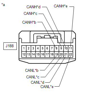
*a | Front view of wire harness connector
(to No. 3 CAN Junction Connector) | |
*b | to 4 Wheel Drive Control ECU (4WD Control ECU) (for 4WD) | |
*c | to No. 4 CAN Junction Connector | |
*d | to Brake Control with Bracket Relay (w/ Trailer Brake Control System) | |
*e | to Central Gateway ECU (Network Gateway ECU) | | |
(b) Measure the resistance according to the value(s) in the table below.
Standard Resistance: |
Tester Connection | Condition |
Specified Condition | Connected to |
|
*1: for 4WD
*2: w/ Trailer Brake Control System | |
J188-8 (CANH) - J188-19 (CANL) |
Cable disconnected from negative (-) battery terminal |
200 Ω or higher | 4 wheel drive control ECU (4WD control ECU)*1 | |
J188-9 (CANH) - J188-20 (CANL) |
Cable disconnected from negative (-) battery terminal |
108 to 132 Ω | No. 4 CAN junction connector | |
J188-10 (CANH) - J188-21 (CANL) |
Cable disconnected from negative (-) battery terminal |
200 Ω or higher | Brake control with bracket relay*2 | |
J188-11 (CANH) - J188-22 (CANL) |
Cable disconnected from negative (-) battery terminal |
108 to 132 Ω | Central gateway ECU (network gateway ECU) |
|
Result | Proceed to | |
OK | A | |
NG (Central gateway ECU [network gateway ECU] CAN main wire) |
B | | NG (No. 4 CAN junction connector CAN main wire) |
C | | NG (Wire to ECU or sensor) |
D |
| A |
| REPLACE NO. 3 CAN JUNCTION CONNECTOR |
| C |
| REPAIR OR REPLACE CAN MAIN WIRE OR CONNECTOR (NO. 3 CAN JUNCTION CONNECTOR - NO. 4 CAN JUNCTION CONNECTOR) |
| D |
| GO TO STEP 10 |
|
B | |
| |
(a) Reconnect the J188 No. 3 CAN junction connector.
|
NEXT | |
| |
| 5. |
CHECK FOR OPEN IN CAN BUS WIRE (CENTRAL GATEWAY ECU [NETWORK GATEWAY ECU] - NO. 3 CAN JUNCTION CONNECTOR) |
| (a) Disconnect the central gateway ECU (network gateway ECU) connector. |
 |
|
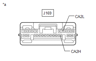
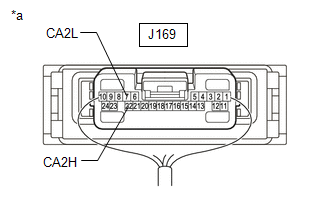
*a | Front view of wire harness connector
(to Central Gateway ECU [Network Gateway ECU]) | | |
(b) Measure the resistance according to the value(s) in the table below.
Standard Resistance: |
Tester Connection | Condition |
Specified Condition | |
J169-22 (CA2H) - J169-7 (CA2L) |
Cable disconnected from negative (-) battery terminal |
108 to 132 Ω |
| OK |
| REPLACE CENTRAL GATEWAY ECU (NETWORK GATEWAY ECU) |
| NG |
| REPAIR OR REPLACE CAN MAIN WIRE OR CONNECTOR (CENTRAL GATEWAY ECU [NETWORK GATEWAY ECU] - NO. 3 CAN JUNCTION CONNECTOR) |
(a) Reconnect the J190 No. 4 CAN junction terminal connector.
|
NEXT | |
| |
| 7. |
CHECK FOR SHORT IN CAN BUS WIRES (NO. 6 CAN JUNCTION CONNECTOR) |
| (a) Disconnect the No. 6 CAN junction connector. |
 |
|
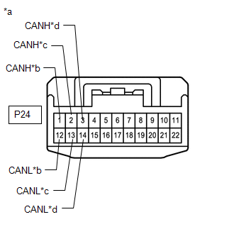
*a | Front view of wire harness connector
(to No. 6 CAN Junction Connector) | |
*b | to Tire Pressure Warning ECU and Receiver | |
*c | to Airbag Sensor Assembly | |
*d | to No. 4 CAN Junction Connector | | |
(b) Measure the resistance according to the value(s) in the table below.
Standard Resistance: |
Tester Connection | Condition |
Specified Condition | Connected to | |
P24-1 (CANH) - P24-12 (CANL) |
Cable disconnected from negative (-) battery terminal |
200 Ω or higher | Tire pressure warning ECU and receiver | |
P24-2 (CANH) - P24-13 (CANL) |
Cable disconnected from negative (-) battery terminal |
108 to 132 Ω | Airbag sensor assembly | |
P24-3 (CANH) - P24-14 (CANL) |
Cable disconnected from negative (-) battery terminal |
108 to 132 Ω | No. 4 CAN junction connector |
|
Result | Proceed to | |
OK | A | |
NG (No. 4 CAN junction connector CAN main wire) |
B | | NG (Airbag sensor assembly CAN main wire) |
C | | NG (Wire to ECU or sensor) |
D |
| A |
| REPLACE NO. 6 CAN JUNCTION CONNECTOR |
| B |
| REPAIR OR REPLACE CAN MAIN WIRE OR CONNECTOR (NO. 6 CAN JUNCTION CONNECTOR - NO. 4 CAN JUNCTION CONNECTOR) |
| D |
| GO TO STEP 10 |
|
C | |
| |
(a) Reconnect the P24 No. 6 CAN junction connector.
|
NEXT | |
| |
| 9. |
CHECK FOR OPEN IN CAN BUS WIRE (AIRBAG SENSOR ASSEMBLY - NO. 6 CAN JUNCTION CONNECTOR) |
| (a) Disconnect the airbag sensor assembly connector. Click here
 |
 |
|
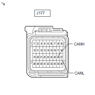
*a | Front view of wire harness connector
(to Airbag Sensor Assembly) | | |
(b) Measure the resistance according to the value(s) in the table below.
Standard Resistance: |
Tester Connection | Condition |
Specified Condition | |
J177-26 (CANH) - J177-27 (CANL) |
Cable disconnected from negative (-) battery terminal |
108 to 132 Ω |
| OK |
| REPLACE AIRBAG SENSOR ASSEMBLY |
| NG |
| REPLACE CAN MAIN WIRE AND CONNECTOR (AIRBAG SENSOR ASSEMBLY - NO. 6 CAN JUNCTION CONNECTOR) |
| 10. |
CHECK FOR SHORT IN CAN BUS WIRES (ECU, SENSOR) |
(a) Reconnect all wire harness connectors. (b)
Disconnect the connector that includes terminals CANH and CANL from the
ECU or sensor to which the short circuited branch line is connected. Click here
| (c) Measure the resistance according to the value(s) in the table below.
Standard Resistance: |
Tester Connection | Condition |
Specified Condition | |
J169-22 (CA2H) - J169-7 (CA2L) |
Cable disconnected from negative (-) battery terminal |
54 to 69 Ω |
HINT:
- If the resistance becomes normal (between 54 and 69 Ω) when the
connector is disconnected from the ECU or sensor, there may be a short
in the ECU or sensor.
- If the resistance does not become normal when the connector is
disconnected from the ECU or sensor, check for a short in the wire
harness and repair or replace the wire harness or connector if
necessary.
|
 |
|
*a | Component with harness connected
(Central Gateway ECU [Network Gateway ECU]) | | |
| OK |
| REPLACE ECU OR SENSOR |
| NG |
| REPAIR OR REPLACE HARNESS OR CONNECTOR | | 

