DESCRIPTION |
Detection Item | Symptom |
Trouble Area | | ECM Communication Stop Mode |
Any of the following conditions are met:
- Communication stop for "ECM (Engine)" is indicated on the "Communication Bus Check" screen of the Techstream.

- Communication system DTCs (DTCs that start with U) that correspond to
"ECM Communication Stop Mode" in "DTC Combination Table" are output.
|
- ECM main wire or connector
- Power source circuit of ECM
- ECM ground circuit
- ECM
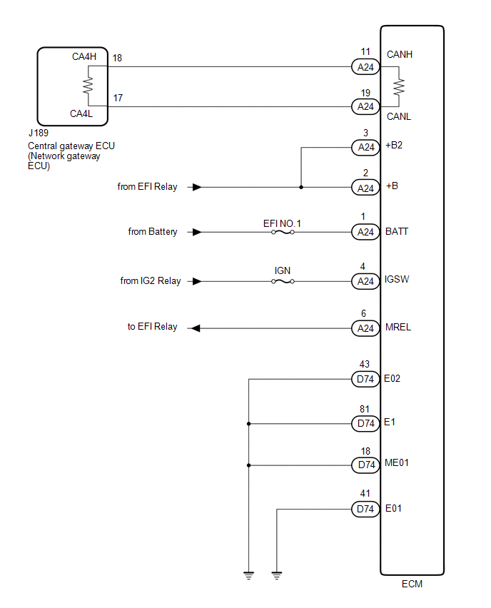
| WIRING DIAGRAM for 1UR-FE:
 for 3UR-FE, 3UR-FBE: for 3UR-FE, 3UR-FBE:
 CAUTION / NOTICE / HINT
CAUTION: When performing the confirmation driving pattern, obey all speed limits and traffic laws.
NOTICE:
HINT:
- Before disconnecting related connectors for inspection, push in on each
connector body to check that the connector is not loose or disconnected.
- When a connector is disconnected, check that the terminals and connector body are not cracked, deformed or corroded.
PROCEDURE
(a) Check vehicle type. Result |
Result | Proceed to | |
for 1UR-FE | A | |
for 3UR-FE, 3UR-FBE | B |
| B |
 | GO TO STEP 3 |
|
A |
 | |
| 2. |
CHECK FOR OPEN IN CAN BUS WIRE (ECM MAIN WIRE) |
(a) Disconnect the cable from the negative (-) battery terminal.
| (b) Disconnect the ECM connector. |
 |
|
*a | Front view of wire harness connector
(to ECM) | | |
(c) Measure the resistance according to the value(s) in the table below.
Standard Resistance: |
Tester Connection | Condition |
Specified Condition | |
A24-10 (CANH) - A24-11 (CANL) |
Cable disconnected from negative (-) battery terminal |
108 to 132 Ω |
| OK |
| GO TO STEP 4 |
| NG |
| REPAIR OR REPLACE CAN MAIN WIRE OR CONNECTOR |
| 3. |
CHECK FOR OPEN IN CAN BUS WIRE (ECM MAIN WIRE) |
(a) Disconnect the cable from the negative (-) battery terminal.
| (b) Disconnect the ECM connector. |
 |
|
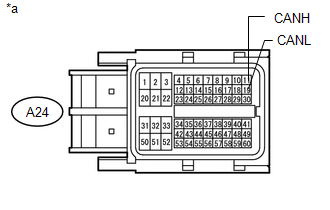
*a | Front view of wire harness connector
(to ECM) | | |
(c) Measure the resistance according to the value(s) in the table below.
Standard Resistance: |
Tester Connection | Condition |
Specified Condition | |
A24-11 (CANH) - A24-19 (CANL) |
Cable disconnected from negative (-) battery terminal |
108 to 132 Ω |
| OK |
| GO TO STEP 5 |
| NG |
| REPAIR OR REPLACE CAN MAIN WIRE OR CONNECTOR |
| 4. |
CHECK HARNESS AND CONNECTOR (POWER SOURCE CIRCUIT) |
(a) Disconnect the ECM connector.
|
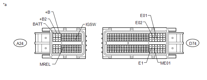
*a | Front view of wire harness connector
(to ECM) | - |
- | (b) Measure the resistance according to the value(s) in the table below.
Standard Resistance: |
Tester Connection | Condition |
Specified Condition | |
D74-42 (E02) - Body ground |
Cable disconnected from negative (-) battery terminal |
Below 1 Ω | |
D74-43 (E01) - Body ground |
Cable disconnected from negative (-) battery terminal |
Below 1 Ω | |
D74-81 (E1) - Body ground |
Cable disconnected from negative (-) battery terminal |
Below 1 Ω | |
D74-82 (ME01) - Body ground |
Cable disconnected from negative (-) battery terminal |
Below 1 Ω | (c) Reconnect the cable to the negative (-) battery terminal.
NOTICE: When disconnecting the cable, some systems need to be initialized after the cable is reconnected.
Click here (d) Measure the voltage according to the value(s) in the table below.
Standard Voltage: |
Tester Connection | Condition |
Specified Condition | |
A24-1 (BATT) - Body ground |
Always | 11 to 14 V | |
A24-2 (+B2) - Body ground | Battery positive (+) voltage applied to terminal A24-34 (MREL) |
11 to 14 V | |
A24-3 (+B) - Body ground | Battery positive (+) voltage applied to terminal A24-34 (MREL) |
11 to 14 V | |
A24-28 (IGSW) - Body ground |
Ignition switch ON | 11 to 14 V | |
Ignition switch off | Below 1 V |
| OK |
| REPLACE ECM |
| NG |
| REPAIR OR REPLACE HARNESS OR CONNECTOR (POWER SOURCE CIRCUIT) |
| 5. |
CHECK HARNESS AND CONNECTOR (POWER SOURCE CIRCUIT) |
(a) Disconnect the ECM connector.
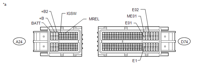
|
*a | Front view of wire harness connector
(to ECM) | - |
- | (b) Measure the resistance according to the value(s) in the table below.
Standard Resistance: |
Tester Connection | Condition |
Specified Condition | |
D74-43 (E02) - Body ground |
Cable disconnected from negative (-) battery terminal |
Below 1 Ω | |
D74-41 (E01) - Body ground |
Cable disconnected from negative (-) battery terminal |
Below 1 Ω | |
D74-81 (E1) - Body ground |
Cable disconnected from negative (-) battery terminal |
Below 1 Ω | |
D74-18 (ME01) - Body ground |
Cable disconnected from negative (-) battery terminal |
Below 1 Ω | (c) Reconnect the cable to the negative (-) battery terminal.
NOTICE: When disconnecting the cable, some systems need to be initialized after the cable is reconnected.
Click here (d) Measure the voltage according to the value(s) in the table below.
Standard Voltage: |
Tester Connection | Condition |
Specified Condition | |
A24-1 (BATT) - Body ground |
Always | 11 to 14 V | |
A24-3 (+B2) - Body ground | Battery positive (+) voltage applied to terminal A24-6 (MREL) |
11 to 14 V | |
A24-2 (+B) - Body ground | Battery positive (+) voltage applied to terminal A24-6 (MREL) |
11 to 14 V | |
A24-4 (IGSW) - Body ground |
Ignition switch ON | 11 to 14 V | |
Ignition switch off | Below 1 V | Result |
Result | Proceed to | |
OK (for 3UR-FE) | A | |
OK (for 3UR-FBE) | B | |
NG | C |
| A |
| REPLACE ECM |
| B |
| REPLACE ECM |
| C |
| REPAIR OR REPLACE HARNESS OR CONNECTOR (POWER SOURCE CIRCUIT) | | 

