PARTS LOCATION ILLUSTRATION 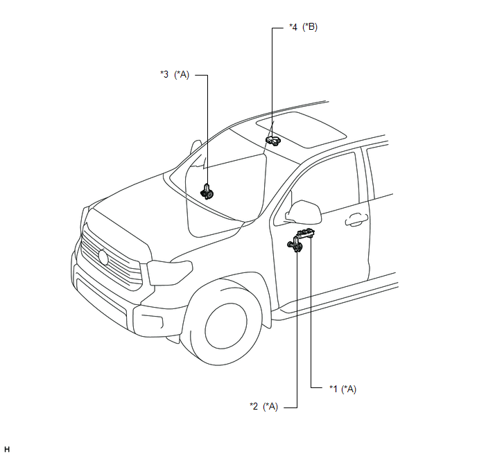
ILLUSTRATION 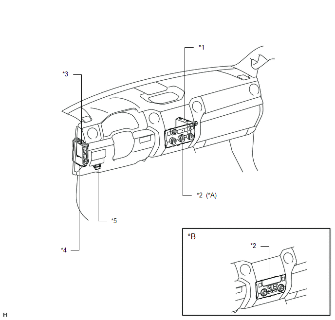
|
Toyota Tundra Service Manual > Automatic Transmission System: System Description
SYSTEM DESCRIPTION 1. SYSTEM DESCRIPTION (a) The Electronic Controlled Automatic Transmission (ECT) is an automatic transmission that electronically controls shift timing using the Engine Control Module (ECM). The ECM detects electrical signals that indicate engine and driving conditions, and contro ...


