COMPONENTS ILLUSTRATION 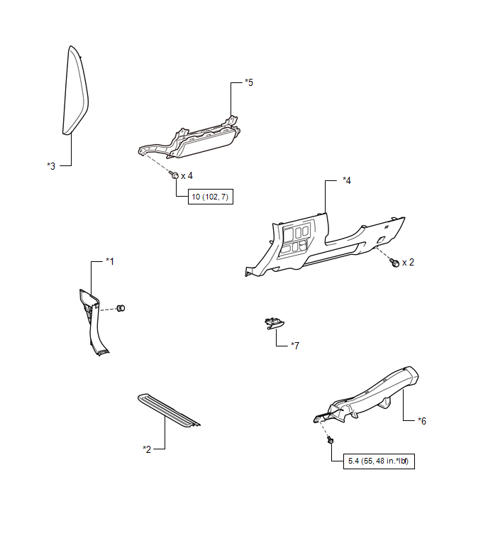
ILLUSTRATION 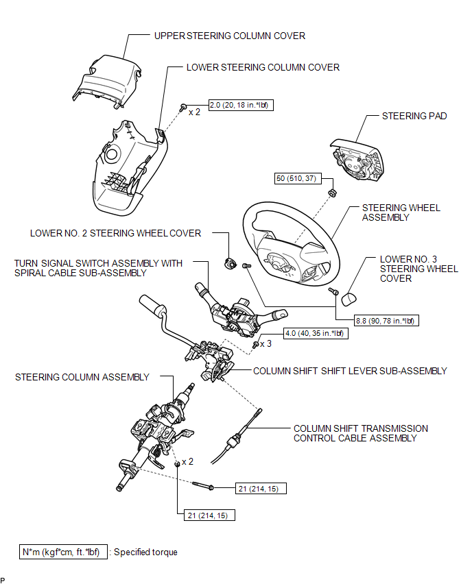 ILLUSTRATION 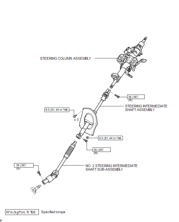 ILLUSTRATION 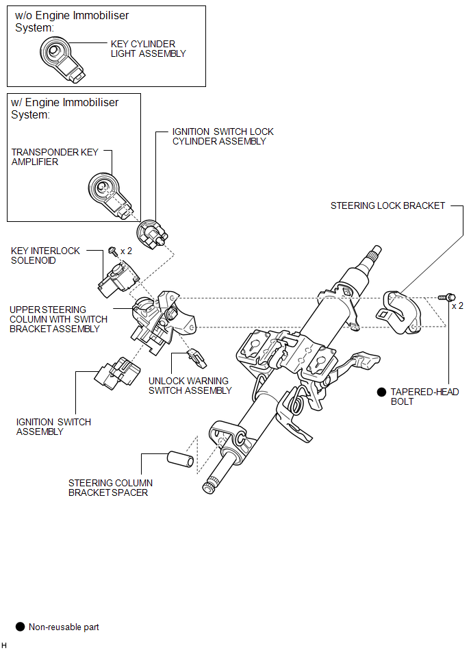 |
Toyota Tundra Service Manual > Navigation System: Precaution
PRECAUTION 1. PRECAUTION FOR DISCONNECTING CABLE FROM NEGATIVE BATTERY TERMINAL NOTICE: After the ignition switch is turned off, the navigation system requires approximately a minute to record various types of memory and settings. As a result, after turning the ignition switch off, wait a minute or ...


