REMOVAL CAUTION / NOTICE / HINT CAUTION: Some
of these service operations affect the SRS airbag system. Read the
precautionary notices concerning the SRS airbag system before servicing
the steering column (See page PROCEDURE 1. PRECAUTION NOTICE: After
turning the ignition switch off, waiting time may be required before
disconnecting the cable from the battery terminal. Therefore, make sure
to read the disconnecting the cable from the battery terminal notice
before proceeding with work (See page 2. PLACE FRONT WHEELS FACING STRAIGHT AHEAD 3. DISCONNECT CABLE FROM NEGATIVE BATTERY TERMINAL CAUTION: Wait at least 90 seconds after disconnecting the cable from the negative (-) battery terminal to prevent airbag and seat belt pretensioner activation. 4. REMOVE LOWER NO. 3 STEERING WHEEL COVER
5. REMOVE LOWER NO. 2 STEERING WHEEL COVER 6. REMOVE STEERING PAD
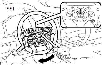
7. REMOVE STEERING WHEEL ASSEMBLY (a) Remove the steering wheel set nut.
(c) Using SST, remove the steering wheel. SST: 09950-50013 09951-05010 09952-05010 09953-05020 09954-05011 8. REMOVE LOWER STEERING COLUMN COVER
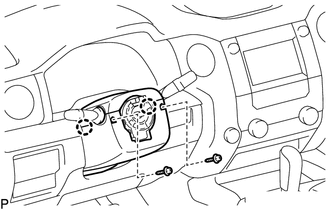
(b) Detach the 2 claws to remove the lower steering column cover. 9. REMOVE UPPER STEERING COLUMN COVER
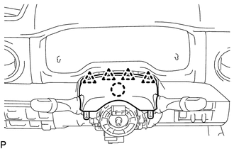
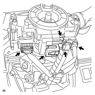
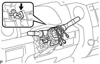
(b) Detach the claw to remove the upper steering column cover. 10. REMOVE TURN SIGNAL SWITCH ASSEMBLY WITH SPIRAL CABLE SUB-ASSEMBLY
11. DISCONNECT COLUMN SHIFT TRANSMISSION CONTROL CABLE ASSEMBLY
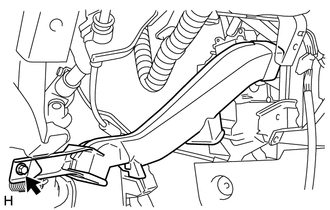
12. REMOVE COLUMN SHIFT SHIFT LEVER SUB-ASSEMBLY 13. REMOVE FRONT DOOR SCUFF PLATE LH 14. REMOVE COWL SIDE TRIM BOARD LH 15. REMOVE INSTRUMENT SIDE PANEL LH 16. REMOVE LOWER INSTRUMENT PANEL FINISH PANEL SUB-ASSEMBLY LH 17. REMOVE LOWER NO. 1 INSTRUMENT PANEL AIRBAG ASSEMBLY 18. REMOVE NO. 3 AIR DUCT SUB-ASSEMBLY
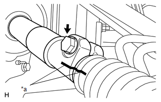
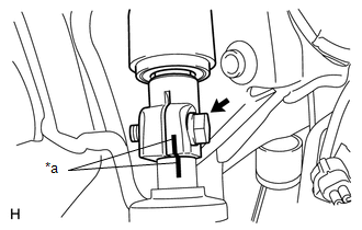
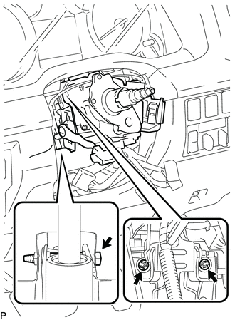
19. REMOVE STEERING INTERMEDIATE SHAFT ASSEMBLY
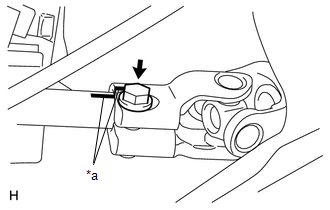
(c) Remove the bolt and steering intermediate shaft from the steering column.
(e) Remove the bolt and steering intermediate shaft from the No. 2 steering intermediate shaft. 20. REMOVE NO. 2 STEERING INTERMEDIATE SHAFT SUB-ASSEMBLY
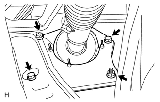
(b) Remove the bolt and No. 2 steering intermediate shaft from the power steering gear. 21. REMOVE STEERING COLUMN ASSEMBLY
|
Toyota Tundra Service Manual > Seat Belt Warning System: Front Passenger Side Seat Belt Warning Light Malfunction
DESCRIPTION When the ignition switch to ON, the occupant detection ECU sends a signal to the center airbag sensor assembly to indicate the state of the front seat inner belt assembly RH and also whether the front passenger seat is occupied. The center airbag sensor assembly sends those signals to th ...

 ).
).