ON-VEHICLE INSPECTION PROCEDURE 1. REMOVE UPPER STEERING COLUMN COVER 2. REMOVE LOWER STEERING COLUMN COVER 3. INSPECT TILT MOTOR
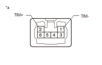
(b) Connect the positive (+) battery terminal to terminal 2 (TIM+) and the negative battery terminal to terminal 1 (TIM-) of the tilt motor connector. Then confirm that the steering wheel tilts up. OK: Steering wheel tilts up. (c) Connect the negative (-) battery terminal to terminal 2 (TIM+) and the positive battery terminal to terminal 1 (TIM-) of the tilt motor connector. Then confirm that the steering wheel tilts down. OK: Steering wheel tilts down. 4. INSPECT TELESCOPIC MOTOR
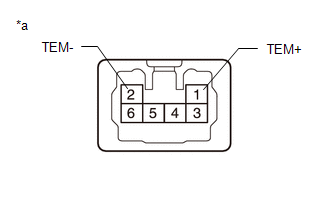
(b) Connect the positive battery terminal to terminal 1 (TEM+) and the negative battery terminal to terminal 2 (TEM-) of the telescopic motor connector. Then confirm that the steering column contracts. OK: Steering column contracts. (c) Connect the negative battery terminal to terminal 1 (TEM+) and the positive battery terminal to terminal 2 (TEM-) of the telescopic motor connector. Then confirm that the steering column extends. OK: Steering column extends. 5. INSTALL LOWER STEERING COLUMN COVER 6. INSTALL UPPER STEERING COLUMN COVER |
Toyota Tundra Service Manual > Rear Seat Assembly(for Crewmax Lh Side): Removal
REMOVAL PROCEDURE 1. REMOVE REAR SEAT ASSEMBLY RH (a) Pull the No. 1 reclining adjuster release handle RH and fold up the seat cushion. (b) Remove the 4 bolts and rear seat assembly RH. NOTICE: Be careful not to damage the vehicle body. 2. REMOVE REAR SEAT INNER BELT ASSEMBLY (a) Remove the bolt. (b ...