Toyota Tundra Service Manual: Solar Sensor Circuit (Driver Side) (B1424/24)

DESCRIPTION

The solar sensor, which is installed on the upper side of the instrument panel, detects sunlight and controls the air conditioning in AUTO mode. The output current from the solar sensor varies according to the amount of sunlight. When the sunlight increases, the output current increases. As the sunlight decreases, the output current decreases. The air conditioning amplifier detects output current from the solar sensor.
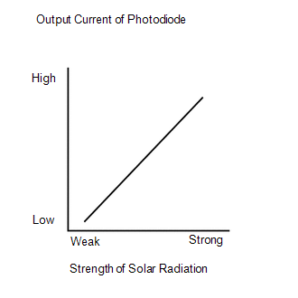
DTC Code

DTC Detection Condition

Trouble Area

B1424/24

Open or short in driver side solar sensor circuit

  • Automatic light control sensor (solar sensor)
  • Harness or connector between solar sensor and air conditioning amplifier
  • Harness and connector between solar sensor and main body ECU
  • Main body ECU
  • Air conditioning amplifier

WIRING DIAGRAM

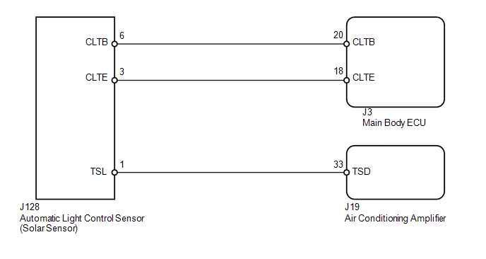
CAUTION / NOTICE / HINT

HINT:

If DTC B1244 is output at the same time, troubleshoot DTC B1244 first (see page ).

PROCEDURE

1.

READ VALUE USING TECHSTREAM (SOLAR SENSOR (for Driver Side))

(a) Use the Data List to check if the driver side solar sensor is functioning properly.

Air Conditioner

Tester Display

Measurement Item / Range

Normal Condition

Diagnostic Note

Solar Sensor (D Side)

Driver side solar sensor /

Min.: 0

Max.: 255

Driver side solar sensor voltage increases as brightness increases

Open in circuit: 0

Short in circuit: 255

OK:

The display is as specified in the normal condition.

Result

Result

Proceed to

NG

A

OK (Checking from the PROBLEM SYMPTOMS TABLE)

B

OK (Checking from the DTC)

C

B

PROCEED TO NEXT CIRCUIT INSPECTION SHOWN IN PROBLEM SYMPTOMS TABLE

C

REPLACE AIR CONDITIONING AMPLIFIER

A

2.

CHECK HARNESS AND CONNECTOR (SOLAR SENSOR)

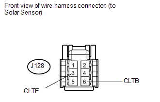
(a) Disconnect the J128 solar sensor connector.

(b) Measure the resistance according to the value(s) in the table below.

Standard resistance:

Tester Connection

Condition

Specified Condition

J128-3 (CLTE) - Body ground

Always

Below 1 Ω

(c) Measure the voltage according to the value(s) in the table below.

Standard voltage:

Tester Connection

Switch Condition

Specified Condition

J128-6 (CLTB) - J128-3 (CLTE)

Ignition switch ON

11 to 14 V

Ignition switch OFF

Below 1 V

NG

GO TO STEP 5

OK

3.

CHECK HARNESS AND CONNECTOR (AIR CONDITIONING AMPLIFIER - SOLAR SENSOR)

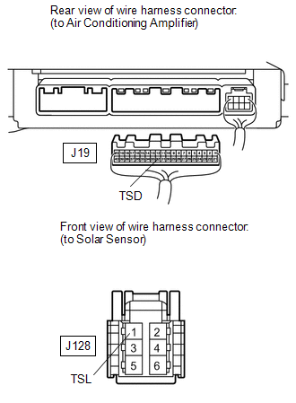
(a) Disconnect the J19 air conditioning amplifier connector.

(b) Disconnect the J128 solar sensor connector.

(c) Measure the resistance according to the value(s) in the table below.

Standard resistance:

Tester Connection

Condition

Specified Condition

J19-33 (TSD) - J128-1 (TSL)

Always

Below 1 Ω

J19-33 (TSD) or J128-1 (TSL) - Body ground

Always

10 kΩ or higher

NG

REPAIR OR REPLACE HARNESS OR CONNECTOR

OK

4.

CHECK AUTOMATIC LIGHT CONTROL SENSOR (SOLAR SENSOR (TSL - CLTE VOLTAGE))

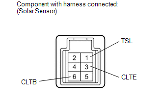
(a) Remove the solar sensor with its connector still connected (see page ).

(b) Apply battery voltage between terminals 6 (CLTB) and 3 (CLTE) of the solar sensor.

(c) Measure the voltage according to the value(s) in the table below.

Standard voltage:

Tester Connection

Condition

Specified Condition

1 (TSL) - 3 (CLTE)

Sensor is subjected to electric light

0.8 to 4.3 V

Sensor is covered with a cloth

Below 0.8 V

HINT:

  • As the inspection light is moved away from the sensor, the voltage decreases.
  • Use an incandescent light for inspection. Bring it approximately 30 cm (11.8 in.) from the solar sensor.
OK

REPLACE AIR CONDITIONING AMPLIFIER

NG

REPLACE AUTOMATIC LIGHT CONTROL SENSOR (SOLAR SENSOR)

5.

CHECK HARNESS AND CONNECTOR (MAIN BODY ECU - SOLAR SENSOR AND BODY GROUND)

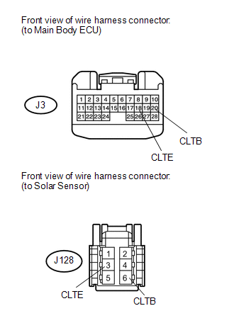
(a) Disconnect the J3 ECU connector.

(b) Disconnect the J128 solar sensor connector.

(c) Measure the resistance according to the value(s) in the table below.

Standard resistance:

Tester Connection

Condition

Specified Condition

J3-18 (CLTE) - J128-3 (CLTE)

Always

Below 1 Ω

J3-20 (CLTB) - J128-6 (CLTB)

J3-18 (CLTE) or J128-3 (CLTE) - Body ground

Always

10 kΩ or higher

J3-20 (CLTB) or J128-6 (CLTB) - Body ground

OK

REPLACE MAIN BODY ECU

NG

REPAIR OR REPLACE HARNESS OR CONNECTOR

    Pressure Sensor Circuit (B1423/23)

    Air Mix Damper Control Servo Motor Circuit (Passenger Side) (B1441/41)

    See More:

    Toyota Tundra Service Manual > Automatic Transmission System: System Description
    SYSTEM DESCRIPTION 1. SYSTEM DESCRIPTION (a) The Electronic Controlled Automatic Transmission (ECT) is an automatic transmission that electronically controls shift timing using the Engine Control Module (ECM). The ECM detects electrical signals that indicate engine and driving conditions, and contro ...

    Toyota Tundra Owners Manual

    Toyota Tundra Service Manual

    © 2024 Copyright www.ttundra.com
    0.0112