DESCRIPTION This circuit provides power to operate the air conditioning amplifier. WIRING DIAGRAM 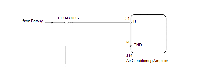
PROCEDURE
(a) Remove the ECU-B NO.2 fuse from the driver side junction block. (b) Measure the resistance according to the value(s) in the table below. Standard resistance:
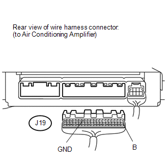
(a) Disconnect the J19 air conditioning amplifier connector. (b) Measure the resistance and voltage according to the value(s) in the table below. Standard resistance:
Standard voltage:
|
Toyota Tundra Service Manual > Sfi System: Internal Control Module Accelerator Pedal Position Performance (P060D)
DESCRIPTION The ECM monitors the input signals of the Accelerator Pedal Position (APP) sensor No. 1. When the input signals and control signals deviate, a DTC is output. DTC No. DTC Detection Condition Trouble Area P060D When either condition below is met: ECM main CPU error ECM sub CPU error (1 tri ...


