DESCRIPTION When the ignition switch is turned ON, positive (+) battery voltage is applied to the air conditioning amplifier. WIRING DIAGRAM 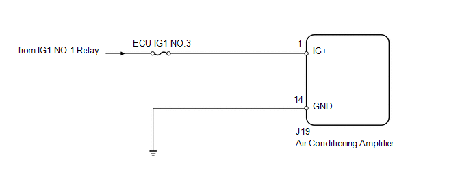
PROCEDURE
(a) Remove the ECU-IG1 NO.3 fuse from the driver side junction block. (b) Measure the resistance according to the value(s) in the table below. Standard resistance:
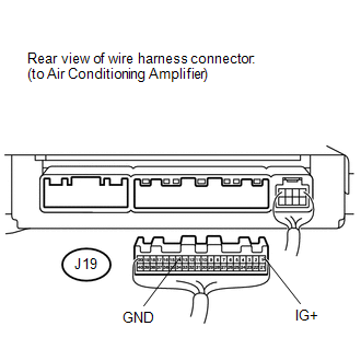
(a) Disconnect the J19 air conditioning amplifier connector. (b) Measure the resistance and voltage according to the value(s) in the table below. Standard resistance:
Standard voltage:
|
Toyota Tundra Service Manual > Front Door Speaker(for Crewmax): Installation
INSTALLATION CAUTION / NOTICE / HINT HINT: Use the same procedure for the RH and LH sides. The procedure listed below is for the LH side. PROCEDURE 1. INSTALL FRONT NO. 3 SPEAKER ASSEMBLY (for 12 Speakers) (a) Attach the 3 claws to install the front No. 3 speaker assembly to the bracket. NOTICE: Do ...


