
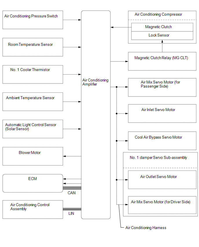
Toyota Tundra Service Manual: System Diagram

SYSTEM DIAGRAM

Communication table

Sender

Receiver

Signal

Line

Air Conditioning Control Assembly

Air Conditioning Amplifier

Air conditioning control signal

LIN

ECM

Air Conditioning Amplifier

  • Engine speed
  • Engine coolant temperature signal

CAN

    System Description

    Terminals Of Ecu

    See More:

    Toyota Tundra Service Manual > Can Communication System: Check Bus 3 Line for Short to +B
    DESCRIPTION There may be a short circuit between one of the CAN bus wires and +B when no resistance exists between terminal 6 (CA3H) of the central gateway ECU (network gateway ECU) and terminal 16 (BAT) of the DLC3, or terminal 21 (CA3L) of the central gateway ECU (network gateway ECU) and terminal ...

    Toyota Tundra Owners Manual

    Toyota Tundra Service Manual

    © 2026 Copyright www.ttundra.com
    0.0266