
DESCRIPTION The ambient temperature sensor is installed in front of the condenser to detect the ambient temperature. This sensor is connected to the air conditioning amplifier and detects fluctuations in the ambient temperature. This data is used for controlling the cabin temperature. The sensor sends a signal to the air conditioning amplifier. The resistance of the ambient temperature sensor changes in accordance with the ambient temperature. As the temperature decreases, the resistance increases. As the temperature increases, the resistance decreases. The air conditioning amplifier applies voltage (5 V) to the ambient temperature sensor and reads voltage changes as the resistance of the ambient temperature sensor changes.
WIRING DIAGRAM 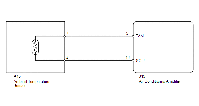
PROCEDURE
(a) Use the Data List to check if the ambient temperature sensor is functioning properly. Air Conditioner
OK: The display is as specified in the normal condition. Result
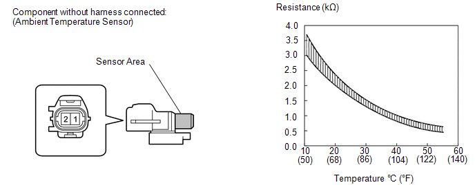
(a) Remove the ambient temperature sensor (see page
(b) Measure the resistance according to the value(s) in the table below. Standard resistance:
NOTICE:
HINT: As the temperature increases, the resistance decreases (see the graph).
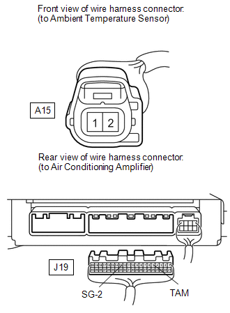
(a) Disconnect the A15 sensor connector. (b) Disconnect the J19 air conditioning amplifier connector. (c) Measure the resistance according to the value(s) in the table below. Standard resistance:
|
Toyota Tundra Service Manual > Power Mirror Control System(w/ Memory): Power Mirrors do not Return to Memorized Position
DESCRIPTION If any of the M1 or M2 seat memory switch is pressed, the outer mirror control ECU assembly LH detects the switch operation and sends the seat memory switch signal to the main body ECU (multiplex network body ECU) via CAN communication. The main body ECU (multiplex network body ECU) send ...


