Toyota Tundra Service Manual: ECU Power Source Circuit

DESCRIPTION

This circuit provides power to operate the air conditioning amplifier.

WIRING DIAGRAM
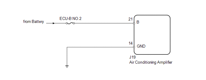
PROCEDURE

1.

INSPECT FUSE (ECU-B NO.2)

(a) Remove the ECU-B NO.2 fuse from the driver side junction block.

(b) Measure the resistance according to the value(s) in the table below.

Standard resistance:

Tester Connection

Condition

Specified Condition

ECU-B NO.2 fuse

Always

Below 1 Ω

NG

REPLACE FUSE

OK

2.

CHECK HARNESS AND CONNECTOR (AIR CONDITIONING AMPLIFIER - BATTERY AND BODY GROUND)

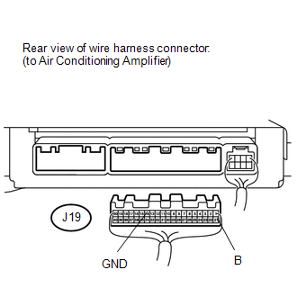
(a) Disconnect the J19 air conditioning amplifier connector.

(b) Measure the resistance and voltage according to the value(s) in the table below.

Standard resistance:

Tester Connection

Condition

Specified Condition

J19-14 (GND) - Body ground

Always

Below 1 Ω

Standard voltage:

Tester Connection

Condition

Specified Condition

J19-21 (B) - Body ground

Always

11 to 14 V

OK

PROCEED TO NEXT CIRCUIT INSPECTION SHOWN IN PROBLEM SYMPTOMS TABLE

NG

REPAIR OR REPLACE HARNESS OR CONNECTOR

    Dtc Check / Clear

    How To Proceed With Troubleshooting

    See More:

    Toyota Tundra Service Manual > Can Communication System: ECU Malfunction (B1003)
    DESCRIPTION DTC No. Detection Item DTC Detection Condition Trouble Area B1003 ECU Malfunction A malfunction in the non-volatile storage of the central gateway ECU (network gateway ECU) is detected. Central gateway ECU (network gateway ECU) PROCEDURE 1. RECONFIRM DTC OUTPUT (a) Connect the Techstream ...

    Toyota Tundra Owners Manual

    Toyota Tundra Service Manual

    © 2024 Copyright www.ttundra.com
    0.0336