DESCRIPTION When the ignition switch is turned ON, positive (+) battery voltage is applied to the air conditioning amplifier. WIRING DIAGRAM 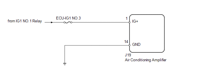
PROCEDURE
(a) Remove the ECU-IG1 NO.3 fuse from the driver side junction block. (b) Measure the resistance according to the value(s) in the table below. Standard resistance:
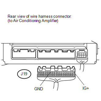
(a) Disconnect the J19 air conditioning amplifier connector. (b) Measure the resistance and voltage according to the value(s) in the table below. Standard resistance:
Standard voltage:
|
Toyota Tundra Service Manual > Sfi System: Crankshaft Position - Camshaft Position Correlation (Bank 1 Sensor A) (P0016-P0019)
DESCRIPTION In the VVT (Variable Valve Timing) system, the appropriate intake and exhaust valve open and close timing is controlled by the ECM. The ECM performs intake and exhaust valve control by performing the following: 1) controlling the camshaft and camshaft timing oil control valve, and operat ...


