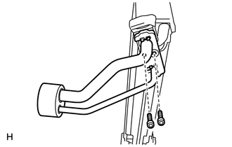
REASSEMBLY PROCEDURE 1. INSTALL COOLER EXPANSION VALVE
(b) Install the 2 O-rings to the No. 1 cooler evaporator sub-assembly. (c) Install the 2 O-rings to the tube and accessory. (d) Install the cooler expansion valve and tube and accessory to the No. 1 cooler evaporator sub-assembly. (e) Using a 4 mm hexagon wrench, install the 2 bolts. Torque: 3.5 N·m {36 kgf·cm, 31 in·lbf} 2. INSTALL NO. 1 COOLER THERMISTOR
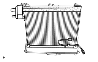
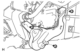
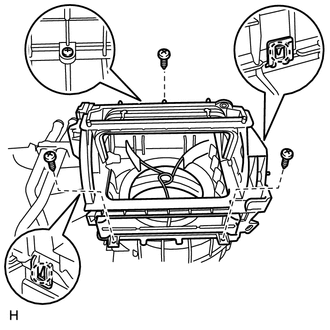
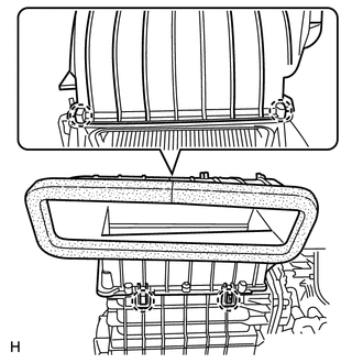
3. INSTALL NO. 1 COOLER EVAPORATOR SUB-ASSEMBLY
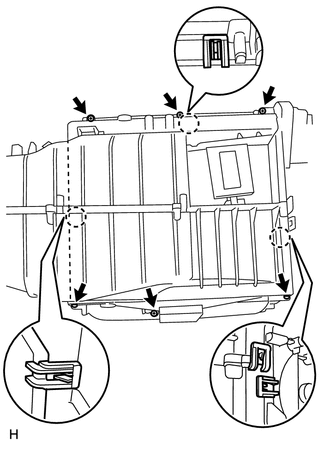
(c) Install the 6 screws and attach the 3 claws.
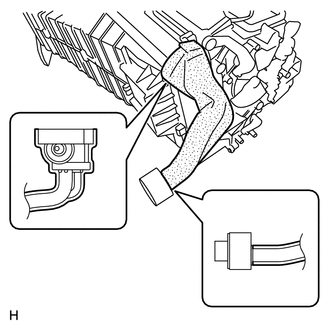
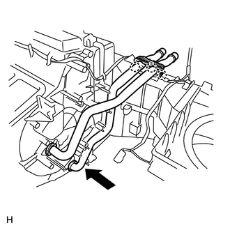
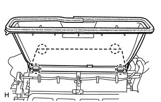
4. INSTALL HEATER RADIATOR UNIT SUB-ASSEMBLY
(b) Attach the 3 claws to install the heater clamp.
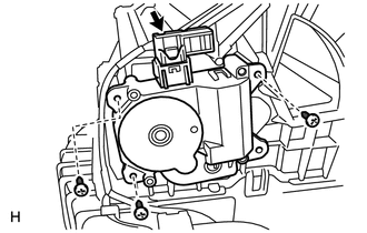
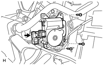
5. INSTALL COOLING UNIT DAMPER SERVO SUB-ASSEMBLY (for Automatic Air Conditioning System)
(b) Connect the connector. 6. INSTALL BLOWER DAMPER SERVO SUB-ASSEMBLY
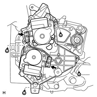
(b) Connect the connector. 7. INSTALL BLOWER UPPER CASE SUB-ASSEMBLY
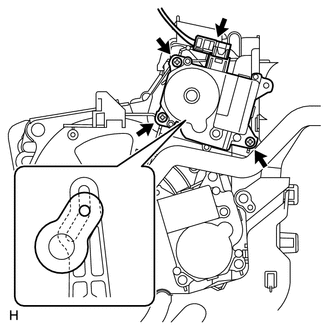
(b) Install the 3 screws. 8. INSTALL DAMPER SERVO SUB-ASSEMBLY (for Automatic Air Conditioning System)
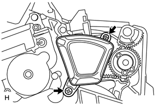
(b) Connect the connector. 9. INSTALL NO. 1 DAMPER SERVO SUB-ASSEMBLY (a) Set the No. 1 damper servo sub-assembly so that the cutout part engages with the tooth of the gear, and attach the claw to install the No. 1 damper servo sub-assembly. 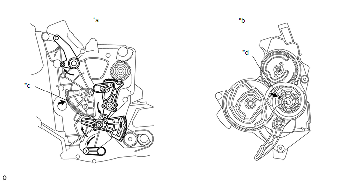
10. INSTALL AIR DUCT
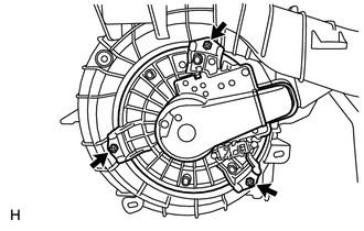
11. INSTALL BLOWER WITH FAN MOTOR SUB-ASSEMBLY
12. INSTALL AIR CONDITIONING AMPLIFIER ASSEMBLY
13. INSTALL NO. 3 AIR DUCT SUB-ASSEMBLY
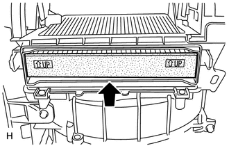
14. INSTALL CLEAN AIR FILTER
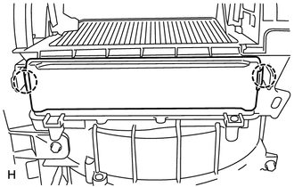
15. INSTALL AIR FILTER COVER PLATE
16. INSTALL NO. 1 AIR DUCT SUB-ASSEMBLY
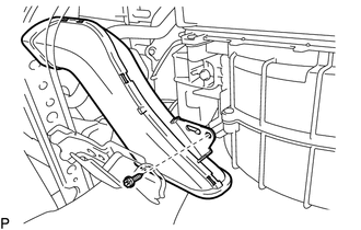
17. INSTALL LOWER DEFROSTER NOZZLE ASSEMBLY
|
Toyota Tundra Service Manual > Front Seat Cushion Heater(for Power Seat): Inspection
INSPECTION PROCEDURE 1. INSPECT FRONT SEAT CUSHION HEATER ASSEMBLY LH (a) Check the resistance of the front seat cushion heater assembly LH. (1) Measure the resistance according to the value(s) in the table below. Standard Resistance: Tester Connection Condition Specified Condition 3 - 5 Seat cushio ...