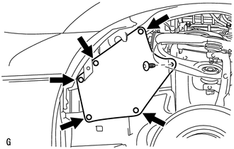
REMOVAL PROCEDURE 1. RECOVER REFRIGERANT FROM REFRIGERATION SYSTEM (a) for HFC-134a(R134a): Click here (b) for HFO-1234yf(R1234yf): Click here 2. REMOVE FRONT FENDER APRON SEAL LH
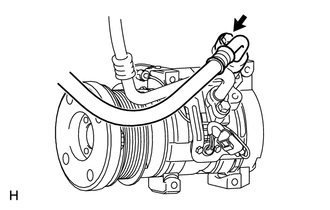
3. REMOVE FAN AND GENERATOR V BELT (a) for 1UR-FE: Click here (b) for 3UR-FE: Click here (c) for 3UR-FBE: Click here 4. DISCONNECT NO. 1 COOLER REFRIGERANT DISCHARGE HOSE
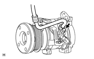
(b) Remove the O-ring from the No. 1 cooler refrigerant discharge hose. NOTICE: Seal the openings of the disconnected parts using vinyl tape to prevent moisture and foreign matter from entering them. 5. DISCONNECT NO. 1 COOLER REFRIGERANT SUCTION HOSE
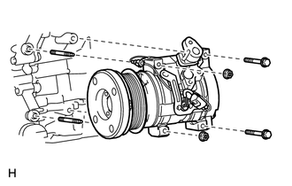
(b) Remove the O-ring from the No. 1 cooler refrigerant suction hose. NOTICE: Seal the openings of the disconnected parts using vinyl tape to prevent moisture and foreign matter from entering them. 6. REMOVE COOLER COMPRESSOR ASSEMBLY
(b) Remove the 2 bolts and 2 nuts. (c) Remove the 2 stud bolts and cooler compressor assembly. |
Toyota Tundra Service Manual > Vehicle Stability Control System: Open in Stop Light Switch Circuit (C1425)
DESCRIPTION The skid control ECU (brake actuator assembly) receives stop light switch assembly signals and uses them to determine whether or not the brakes are applied. The skid control ECU (brake actuator assembly) has a detection circuit that it uses to detect an open in the stop light input line. ...